Boiler step energy using system and method

A boiler and energy utilization technology, which is applied in the field of boiler cascade energy utilization system, can solve the problems such as no guidance on the specific layout position of the waste heat utilization system, complex circuit structure of the compound circulation circuit, and increased equipment investment cost, etc., so as to improve energy utilization efficiency , simple structure, and the effect of improving dust removal efficiency

Inactive Publication Date: 2016-08-10
HUAZHONG UNIV OF SCI & TECH
View PDF5 Cites 2 Cited by
  • Summary
  • Abstract
  • Description
  • Claims
  • Application Information

AI Technical Summary

Problems solved by technology

[0002] At present, the temperature of the flue gas at the tail of the boiler in the power plant is still as high as 130°C after passing through the air preheater and the dust collector. , this part of the heat is not used effectively and is directly lost, which reduces the energy utilization efficiency
[0003] At present, there are many schemes for industrial waste heat utilization systems in the prior art. For example, CN105298567A discloses an industrial waste heat utilization system using supercritical carbon dioxide working fluid. The compound circulation loop of the compound circulation loop, in which the compound circulation loop of the hierarchical series type includes a generator, a turbine, a regenerator, a cooler and a compressor. After passing through the turbine in the system, the working medium needs to be reheated by two regenerators Then through the cooler and the compressor in turn, that is, the working medium is heated first and then cooled, resulting in a waste of energy. It needs to be additionally equipped with a regenerator for heat recovery, and the circuit structure of the compound cycle is complicated, which increases the equipment investment cost. , and it does not give guidance on the specific layout of the waste heat utilization system

Method used


Image

  • Boiler step energy using system and method
  • Boiler step energy using system and method
  • Boiler step energy using system and method

Examples


Embodiment Construction

[0032] In order to make the object, technical solution and advantages of the present invention clearer, the present invention will be further described in detail below in conjunction with the accompanying drawings and embodiments. It should be understood that the specific embodiments described here are only used to explain the present invention, not to limit the present invention. In addition, the technical features involved in the various embodiments of the present invention described below can be combined with each other as long as they do not constitute a conflict with each other.

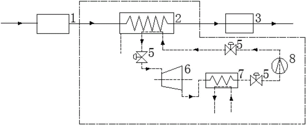
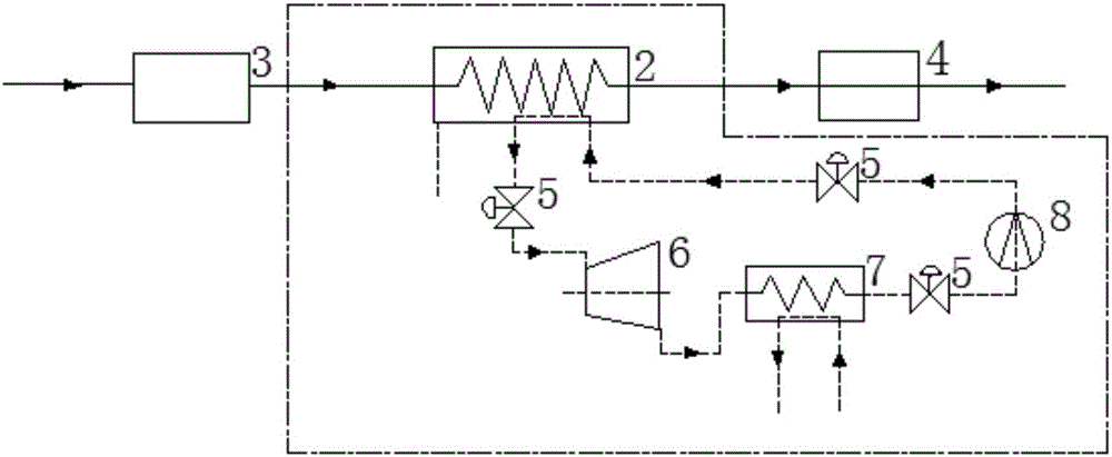
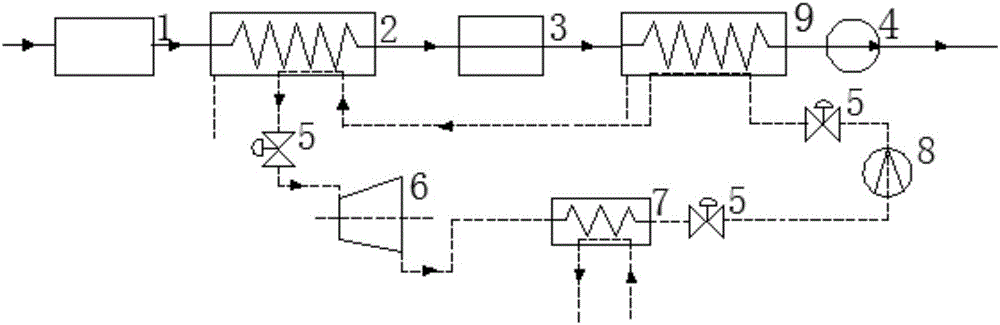
[0033] The basic principle of the present invention is to pass the flue gas at the tail of the high-temperature boiler into the heat exchanger 2 and supercritical CO 2 Perform heat exchange so that part of the flue gas heat is exchanged to supercritical CO 2 , through supercritical CO 2 External work in the steam turbine converts this part of energy into electrical energy or mechanical energy,...


PUM


Abstract

The invention discloses a boiler step energy using system and method. According to the boiler step energy using system and method, boiler tail fume and supercritical CO2 are subjected to heat exchange in a first heat exchanger, so that the temperature of the supercritical CO2 is raised; the warmed supercritical CO2 works outwards through a steam turbine and then is led into a second heat exchanger; and the supercritical CO2 is cooled after subjected to heat exchange with water in the second heat exchanger, and the cooled supercritical CO2 is subjected to isothermal compression in a gas compressor, and then led into the first heat exchanger or led into a third heat exchanger and then led into the first heat exchanger for circulation so as to achieve utilization of waste heat of the smoke. According to the boiler step energy using system and method, efficient and step utilization of the waste heat of the boiler tail fume can be achieved, and the boiler step energy using system and method have the advantages of being environmentally friendly, efficient, simple, low in cost and the like.

Description

technical field [0001] The invention belongs to the technical field of flue gas waste heat utilization, and more specifically relates to a boiler cascade energy utilization system and method. Background technique [0002] At present, the temperature of the flue gas at the tail of the boiler in the power plant is still as high as 130°C after passing through the air preheater and the dust collector. , this part of the heat is not effectively utilized and is directly lost, which reduces the energy utilization efficiency. [0003] At present, there are many schemes for industrial waste heat utilization systems in the prior art. For example, CN105298567A discloses an industrial waste heat utilization system using supercritical carbon dioxide working fluid. The compound circulation loop of the compound circulation loop, in which the compound circulation loop of the hierarchical series type includes a generator, a turbine, a regenerator, a cooler and a compressor. After passing th...

Claims


Application Information

Patent Timeline
Patent Type & Authority Applications(China)
IPC IPC(8): F01K27/02F01K25/10F01K7/32F01D17/10F01D15/08F01D15/10F23J15/06
CPCF01D15/08F01D15/10F01D17/10F01K7/32F01K25/103F01K27/02F23J15/06Y02E20/30
Inventor 向军卿梦霞胡松苏胜汪一徐俊唐浩孙志君
Owner HUAZHONG UNIV OF SCI & TECH
Why Eureka
Try Eureka