
A distributed gas-complementary solar energy combined cooling, heating and power system

A technology of combined cooling, heating and power supply and solar hot water, which is applied in the field of comprehensive utilization of clean energy, can solve the problems of few uses of heat sources, unsatisfactory performance of battery panels, constraints on distributed solar technology, etc., to achieve strong utilization prospects and improve The effect of comprehensive utilization efficiency and efficiency improvement

Active Publication Date: 2021-01-19
国网(天津)综合能源服务有限公司 +5
View PDF6 Cites 0 Cited by
  • Summary
  • Abstract
  • Description
  • Claims
  • Application Information

AI Technical Summary

Problems solved by technology

[0003] However, whether it is a solar photovoltaic thermal system or a household solar hot water system, in summer, when the demand for hot water is not large, the solar thermal collection system is basically idle, and the solar photovoltaic thermal system cannot be brought in time due to the cooling medium. The temperature of the battery board makes the performance of the battery board unsatisfactory
At the same time, the priority is to ensure the power output of the battery panel. The output temperature of the solar photovoltaic thermal cooling medium is generally around 50°C. The heat source of this quality has few uses and cannot meet the heat source temperature requirements of the absorption refrigeration system; in winter, the solar photovoltaic thermal The temperature quality of hot water produced by the system and household solar water heating system cannot meet the needs of users; and the solar energy itself has unstable characteristics, which restrict the development of distributed solar energy technology

Method used


Image

  • A distributed gas-complementary solar energy combined cooling, heating and power system

Examples


Embodiment Construction

[0022] The present invention will be further described in detail below in conjunction with the accompanying drawings and through specific embodiments. The following embodiments are only descriptive, not restrictive, and cannot limit the protection scope of the present invention.

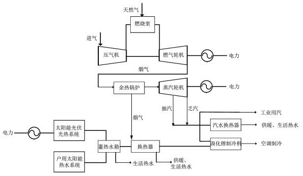
[0023] A combined cooling, heating and power system using distributed gas complementary solar energy, including a distributed gas system, a solar photovoltaic photothermal system, a household solar water heating system, a lithium bromide absorption refrigeration system, and a data acquisition system. The thermal system and the household solar hot water system are connected to the water inlet of the hot water storage tank, and the outlet water of the hot water tank is respectively connected to the domestic water pipeline and the water inlet pipe of the heat exchanger. The flue gas of the waste heat boiler in the distributed gas system is The discharge pipeline is connected to the heat exchanger, and th...


PUM


Abstract

The invention relates to a distributed gas-complementary solar energy combined cooling, heating and power supply system, which includes a distributed gas system, a solar photovoltaic photothermal system, a household solar hot water system, and a lithium bromide absorption refrigeration system. The system and the household solar water heating system are connected to the water inlet of the heat storage tank, the heat storage tank is connected to the cold water inlet of the heat exchanger, the hot water outlet of the heat exchanger is connected to the lithium bromide refrigerator, and the hot gas inlet of the heat exchanger is connected to the The flue gas discharge pipeline of the waste heat boiler in the distributed gas system. The hot water generated by the photothermal system in the solar photovoltaic photothermal system and the household solar hot water system flows into the hot water storage tank, and the hot water flows into the heat exchanger and is heated by the exhaust gas of the distributed gas waste heat boiler. Reach the temperature of the heat source of the lithium bromide refrigerator to realize refrigeration. The system makes full use of the heat generated by the system, and the electricity generated by the system can be used for self-use or connected to the grid. It truly realizes the efficient cascade utilization of clean energy and has a strong utilization prospect.

Description

technical field [0001] The invention belongs to the field of comprehensive utilization of clean energy, and relates to distributed gas, solar photovoltaic photothermal system, household solar hot water system and lithium bromide absorption refrigeration system, especially a distributed gas complementary solar combined cooling, heating and power system . Background technique [0002] In the context of the current rapid development of distributed clean energy, solar energy plays an important role in the distributed energy system due to its universality and sustainability. Its main utilization forms are photovoltaic power generation and household solar water heating system. As the conversion efficiency of photovoltaic power generation is less than 20%, a large amount of solar energy is not used, and this part of the heat is absorbed by the solar panel, and the temperature of the solar panel increases, resulting in a further decrease in the photoelectric conversion efficiency (...

Claims


Application Information

Patent Timeline
Patent Type & Authority Patents(China)
IPC IPC(8): F22B1/18F23J15/06F25B15/06F24D3/02F24D3/08F24S10/00H02S40/44F01K17/02
CPCF01K17/02F22B1/1815F23J15/06F24D3/005F24D3/02F24D3/08F25B15/06F24S10/00H02S40/44Y02B10/10Y02B10/20Y02B10/70Y02B30/00Y02B30/625Y02E10/44Y02E10/50Y02E10/60Y02E20/30
Inventor 艾邓鑫赵亮王成山陈竟成王桂林于建成郭力周连升霍现旭甘智勇边疆
Owner 国网(天津)综合能源服务有限公司
Learn More