
Gas-driven air source heat pump heat supply unit for central heating system

A technology for heating units and driving air, which is applied in heat recovery systems, machines using solar energy, refrigerators, etc. It can solve the problems of thermal power plants with increased emissions, large footprints, and increased total pollution, and achieve thermal energy conversion rates. High efficiency and low running cost

Active Publication Date: 2016-08-10
山东生态家园环保股份有限公司
View PDF5 Cites 34 Cited by
  • Summary
  • Abstract
  • Description
  • Claims
  • Application Information

AI Technical Summary

Problems solved by technology

[0004] At present, a large number of air source heat pump units used in regional central heating use electricity as the driving energy, the energy efficiency ratio is about 2-2.5, the maximum water supply temperature is 65°C, and the compressors are mostly fixed-frequency scroll compressors with small capacity. , when it is applied to central heating, the area is too large, and the use of electricity for heating should not be advocated in areas where the grid capacity is insufficient. Moreover, the use of electricity as the driving energy means that the increase in electricity consumption means an increase in the emissions of thermal power plants, which increases the total pollution

Method used


Image

  • Gas-driven air source heat pump heat supply unit for central heating system

Examples


Embodiment Construction

[0022] The present invention will be further described below in conjunction with accompanying drawing and example.

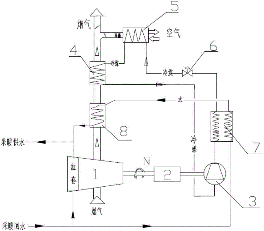
[0023] Such as figure 1 As shown, a gas-driven air source heat pump heating unit for a central heating system includes an internal combustion engine 1 with a cylinder jacket cooling device, a compressor 3, a condenser 7, an evaporator, and a flue gas waste heat recovery device 8 . The compressor 3 is a screw or scroll compressor, and the evaporator includes an evaporator A4 and an evaporator B5. The mechanical energy output end of the internal combustion engine 1 is connected to the compressor 3 through the continuously variable transmission 2, and the flue gas waste heat recovery device 8 and the evaporator A4 are sequentially arranged on the exhaust pipeline of the internal combustion engine 3 to absorb the heat energy of the flue gas. The evaporator B5 is Absorption of thermal energy in the air (defrosting with combustion engine exhaust only part of the tim...


PUM


Abstract

The invention discloses a gas-driven air source heat pump heat supply unit for a central heating system. The gas-driven air source heat pump heat supply unit for the central heating system comprises an internal combustion engine. The internal combustion engine, a compressor, a condenser and a flue gas waste heat recoverer are connected in sequence, so that a gas-heating hot water system is formed. The condenser is further connected with a first evaporator which is connected back to the compressor, so that an air source heat pump refrigerant system is formed. The flue gas waste heat recoverer is arranged on a flue gas pipeline of the internal combustion engine. A water outlet pipeline of the flue gas waste heat recoverer is connected with a water supply pipeline of a heat supply system, and the heat supply system supplies circulating high-temperature water to users. The internal combustion engine is adopted to drive a heat pump to pump heat in air, then waste heat continues to be applied to the heat supply system, the integral heat energy conversion rate can be 200%, and the heat energy conversion rate is high. The outlet water temperature of the condenser can be 60 DEG C or over by increasing the condensation pressure, water discharged out of the condenser further absorbs flue gas heat through the flue gas waste heat recoverer arranged on the exhaust pipeline of the internal combustion engine, and the water supply temperature can be up to 85 DEG C.

Description

technical field [0001] The invention relates to a gas-driven air source heat pump heating unit, in particular to a gas-driven air source heat pump heating unit used in a central heating system. Background technique [0002] Gas engine driven heat pump (GHP abbreviated as GHP) mainly refers to the multi-purpose unit used in multi-connected refrigerant air conditioning system. Its characteristic is that the refrigerant (refrigerant) is used as the circulating medium of the indoor unit, and a piston compressor is generally used. The existing GHP technology can be used for indoor heating through air conditioning, but cannot be used for central heating systems. The main technical reason is that it is limited by the compression ratio and condensation (evaporation) pressure. The optimal design value of the condensation temperature is about 50°C. If the hot water is produced through the plate heat exchanger, the actual water supply temperature is about 45°C, the efficiency is low, ...

Claims


Application Information

Patent Timeline
Patent Type & Authority Applications(China)
IPC IPC(8): F25B27/00F25B41/00F24H4/02F25B41/40
CPCF24H4/02F25B27/005F25B2327/001F25B41/40Y02B30/52Y02P80/15
Inventor 韩广钧刘学来苏保玲
Owner 山东生态家园环保股份有限公司
Learn More