
Intermittent fluidization thermal energy and chemical energy storage and release reaction device and working method

A reaction device and fluidization technology, which is applied in the field of medium and high temperature thermal energy storage, can solve the problems of rarely seen application of high temperature thermochemical energy storage, etc., so as to avoid uneven reaction heat release, make up for unevenness, and reduce industrial pollution. Effect

Active Publication Date: 2016-08-10
SOUTH CHINA UNIV OF TECH
View PDF4 Cites 7 Cited by
  • Summary
  • Abstract
  • Description
  • Claims
  • Application Information

AI Technical Summary

Problems solved by technology

At present, the basic principles of fluidization devices have been popularized and applied in industrial fields: certain physical processes, such as pneumatic conveying, granulation, drying, heat exchange, etc.; fluidized combustion; petrochemical industry; coal gasification; calcination of materials And roasting, etc., but it is rarely seen in the technical field of high-temperature thermochemical energy storage

Method used


Image

  • Intermittent fluidization thermal energy and chemical energy storage and release reaction device and working method
  • Intermittent fluidization thermal energy and chemical energy storage and release reaction device and working method
  • Intermittent fluidization thermal energy and chemical energy storage and release reaction device and working method

Examples


Embodiment Construction

[0039] The above content has fully explained the specific structure of the present invention. The specific implementation will be described in detail below in conjunction with the accompanying drawings, taking the application of the present invention to a 450°C, 0.25MW energy storage and conversion device as an example. Enforcement and protection are not limited thereto.

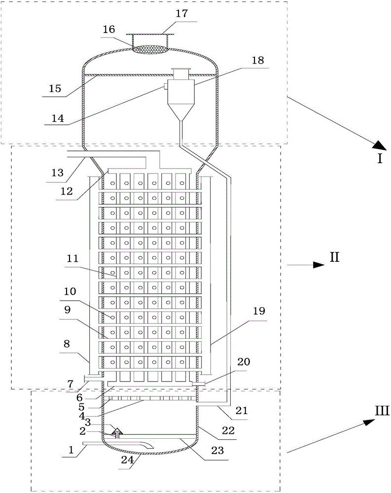
[0040] Such as figure 1 As shown, an intermittent fluidized thermal energy and chemical energy storage and release reaction device includes three parts: fluidization system III, heat exchange system II and gas-solid separation system I. The three systems are all in a fluidized bed inside the device.

[0041] Among them, the fluidization system is at the bottom of the device, the elbow 1 is welded to the gas pre-distribution device 24, and the high-pressure oxygen enters the reaction device through the elbow 1, and after interacting with the gas pre-distribution device 24, it contacts the gas flow distributi...


PUM


Abstract

The invention discloses an intermittent fluidization thermal energy and chemical energy storage and release reaction device and a working method. The device comprises a fluidization system, a heat exchange system and a gas-solid separation system. The fluidization system is located at the bottom of the reaction device. The heat exchange system is located in the middle of the reaction device. The gas-solid separation system is located at the top of the reaction device. The fluidization system is connected with the heat exchange system through an internal horizontal baffle. The heat exchange system is connected with the gas-solid separation system through a cyclone separator. The gas-solid separation system is connected with the fluidization system through an external material guide pipe. According to the intermittent fluidization thermal energy and chemical energy storage and release reaction device and the working method, a thermochemistry energy storage mode is adopted, and the thermal conversion efficiency is high; backmixing of reactants is reduced through an intermittent reaction; the reaction is more sufficient through secondary gas inlet; the energy storage process and the energy release process are conducted independently, and operation is easy; and the gas-solid separation system is arranged internally, so that the separated gas has the advantages of being purer and easy to recycle. The intermittent fluidization thermal energy and chemical energy storage and release reaction device and the working method can be used for occasions of solar-powered Rankine power generation or other large-scale thermal energy storage, and the thermal energy grade is improved.

Description

technical field [0001] The invention belongs to the field of medium-high temperature thermal energy storage, and in particular relates to a device and method for storing and utilizing thermal energy provided by an external heat source into chemical energy in chemical substances by adopting an intermittent fluidization method. Background technique [0002] Because solar energy has the advantages of cleanness, pollution-free, and renewable, more and more people pay attention to it. The large-scale utilization of solar energy is of great significance for solving the problems of environmental pollution, ecological destruction and energy crisis. However, due to the intermittent and discontinuous characteristics of solar energy, which cannot provide energy stably, the large-scale thermal utilization of solar energy is greatly restricted. [0003] At present, there are mainly three heat storage methods in solar thermal utilization, sensible heat energy storage, latent heat energy ...

Claims


Application Information

Patent Timeline
IPC IPC(8): F28D20/00F28D13/00
CPCF28D13/00F28D20/003Y02E60/14
Inventor 龙新峰张丽桦赖永鑫唐永铨廖珊珊
Owner SOUTH CHINA UNIV OF TECH
Learn More