Rapid positioning device and positioning method for optical system test

An optical system and positioning device technology, applied in the field of optical detection, can solve the problems of long preparation time for debugging, waste of time and manpower, etc., and achieve the effects of shortening debugging time, easy replacement, and wide applicability

Inactive Publication Date: 2016-08-10
XI'AN INST OF OPTICS & FINE MECHANICS - CHINESE ACAD OF SCI
View PDF7 Cites 5 Cited by
  • Summary
  • Abstract
  • Description
  • Claims
  • Application Information

AI Technical Summary

Problems solved by technology

[0004] In order to solve the problem of long pre-commissioning preparation time, waste of time and manpower when using the existing automatic detection equipment to detect the optical system, the present invention provides a rapid positioning device and positioning method for optical system testing that can improve the testing efficiency

Method used


Image

  • Rapid positioning device and positioning method for optical system test
  • Rapid positioning device and positioning method for optical system test

Examples


Embodiment Construction

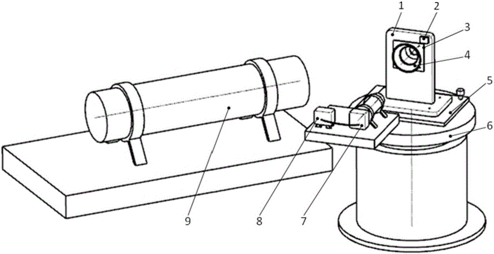
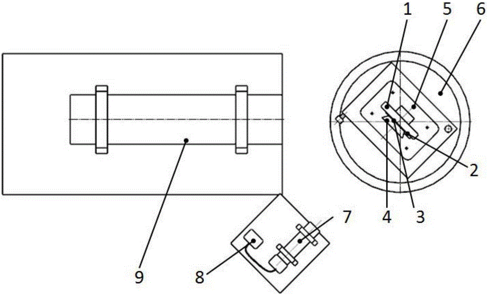
[0033] see figure 1 with figure 2 , provides a schematic diagram of the rapid positioning device for optical system testing of the present invention, the device includes:

[0034] Aiming unit, optical system positioning unit and attitude adjustment unit; Aiming unit comprises self-collimating light pipe 7 and monitor 8; Optical system positioning unit comprises reference plate 1 and reference mirror 2; Attitude adjustment unit comprises two-dimensional adjustment table 5 and single Axis turntable 6; the two-dimensional adjustment table and the reference plate are sequentially arranged on the single-axis turntable from bottom to top; the two-dimensional adjustment table is used to adjust the azimuth and pitch direction of the reference plate. The two-dimensional adjustment table 5 can be adjusted in two directions of azimuth and pitch, and the resolution is better than 1″; the positioning accuracy of the 6-corner position of the single-axis turntable is better than 2″;

[00...


PUM


Abstract

The invention belongs to the optical detection field, and discloses a rapid positioning device and positioning method for optical system test. The positioning device records the test posture of a standard optical system on a test device; after a tested optical system is changed, the posture reappears on the test device; the posture goes through a series of conversion through the positioning device; the normal direction of a benchmark mirror represents the test posture of the optical system, and the optical axis of an auto-collimation light pipe is used as the standard of a standard posture; in replacing the tested optical system again, the posture can reappear only by employing a two-dimensional platform to adjust the benchmark mirror normal to be parallel with the optical axis of an auto-collimation light pipe. The device has the characteristics of simple structure and high positioning accuracy, is suitable for assembly line work of mass products, and can directly perform test of relative specifications after positioning, thereby avoid a debugging process before test in the prior art.

Description

technical field [0001] The invention belongs to the field of optical detection, and relates to a rapid positioning device and a positioning method for optical system testing, which can be applied to rapid and batch detection and positioning of optical systems. Background technique [0002] In the field of optical inspection, especially for some optical systems that will be used in important production or living occasions, in order to judge whether they are qualified or not, some key indicators need to be tested one by one. However, this type of optical system is often mass-produced, so it has the characteristics of a large number of products to be inspected and similar inspection schemes. Before using some automatic detection equipment to detect it, it is necessary to adjust the optical axis of the optical system and the optical axis of the detection equipment to be parallel or coaxial, and different indicators have different requirements for the parallelism of the two axes ...

Claims


Application Information

Patent Timeline
Patent Type & Authority Applications(China)
IPC IPC(8): G01M11/00
CPCG01M11/00
Inventor 张洁焦璐璐张欢赵怀学周艳胡丹丹薛勋郭毅刘峰段亚轩赛建刚
Owner XI'AN INST OF OPTICS & FINE MECHANICS - CHINESE ACAD OF SCI
Why Eureka
Try Eureka