Multi-beam imaging sonar sidelobe suppression method and array sparsity method

A sidelobe suppression and multi-beam technology, applied in the field of signal processing in sonar technology, can solve problems such as sidelobe increase, achieve the effects of reducing running time, realizing array sparseness, and good engineering practicability

Inactive Publication Date: 2016-08-10
NANJING UNIV OF AERONAUTICS & ASTRONAUTICS
View PDF0 Cites 23 Cited by
  • Summary
  • Abstract
  • Description
  • Claims
  • Application Information

AI Technical Summary

Problems solved by technology

[0005] The technical problem to be solved by the present invention is to provide a sidelobe suppression method of multi-beam imaging sonar, which solves the problem of sidelobe increase in the sparse multi-beam array in the prior art

Method used


Image

  • Multi-beam imaging sonar sidelobe suppression method and array sparsity method
  • Multi-beam imaging sonar sidelobe suppression method and array sparsity method
  • Multi-beam imaging sonar sidelobe suppression method and array sparsity method

Examples


specific Embodiment 1

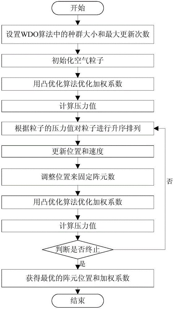
[0051] The sidelobe suppression method of the multi-beam imaging sonar array realizes the sidelobe suppression of the semi-circular array through the given hybrid algorithm based on wind driven optimization (WDO) and convex optimization. In the given hybrid algorithm, the WDO algorithm is used as a global optimization The algorithm searches for the common optimal array element position applicable to all beam directions, and the convex optimization is used as a local optimization algorithm to optimize the weighting coefficients of each beam direction. By using WDO and convex optimization to perform global optimization and local optimization respectively, the proposed hybrid algorithm greatly reduces the possibility of falling into local optimum during the optimization process. The hybrid algorithm includes two stages: in the first stage, the WDO algorithm is used to search for the common optimal array element position applicable to all beam directions; in the second stage, when ...

specific Embodiment 2

[0071] The array sparse method of multi-beam imaging sonar comprises the following steps:

[0072] Step 1. Establish the array sparse model of the multi-beam imaging sonar array under the given main and side lobe performance requirements;

[0073] Sparseness is achieved by extracting part of the array elements from the regular grid on the array, and the binary number '1''0' is used to indicate the presence or absence of array elements in the array. In order to meet the requirement of keeping the width of the main lobe unchanged, the array The two array elements at both ends are reserved (x 1 =x N =1), then the sparse problem is transformed into a mathematical optimization problem under the multi-constraint condition given by (2):

[0074] min | | X 1 | | ...

specific Embodiment 3

[0087] In order to facilitate the understanding of the technical solution, the detailed description will be given below by taking the sparse array based on the multi-beam uniform semicircular array as an example.

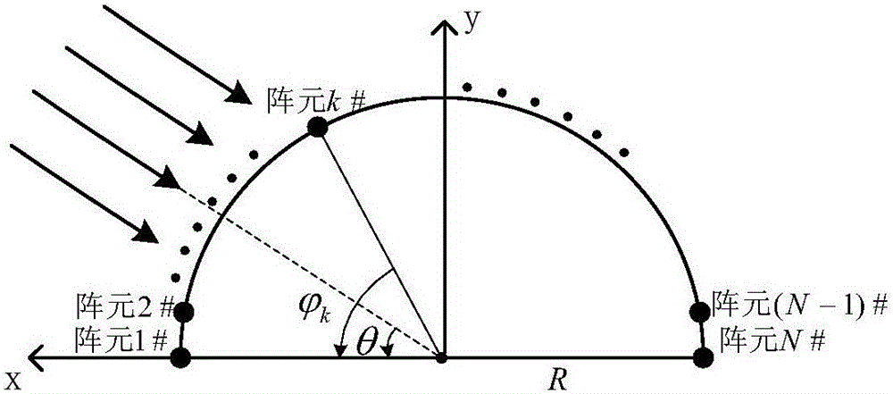
[0088] The semicircular array in this embodiment is as figure 1 As shown, it consists of N uniformly distributed array elements 1#, 2#,...,N#, and the distance between the line connecting the array element k# and the center of the array and the x-axis where the reference array element 1# is located The included angle is Where k=1,2,...,N, θ is the angle of arrival of the signal. Assuming that the uniform semicircular array has a total of 180 array elements, 538 narrow beams are to be generated between 45°-135° in order to scan the direction range, and the sidelobe constraint value of the beam PSLL d Set to -25dB. The array radius R is 0.12m, and the signal wavelength λ is 0.0033m.

[0089] In the WDO algorithm, a population is set to contain 30 particles, and t...


PUM


Abstract

The invention discloses a multi-beam imaging sonar sidelobe suppression method. Via use of a wind-driven optimization algorithm, an optimal array element position suitable for all wave beam directions is searched; via use of a convex optimization algorithm, an optimal weighting coefficient suitable for all wave beam directions is calculated; an array sidelobe is suppressed, possibility of optimization searching processes being trapped in local optimum is greatly reduced, and sidelobe suppression effects are improved. The invention also discloses a multi-beam imaging sonar array sparsity method, via use of an iteration sparsity method based on a mixed algorithm, a multi-beam sidelobe peak value level is suppressed via optimization of array element position arrangement and the weighting coefficient on a precondition that requirements for main sidelobe performance are given, array sparsity is realized on the premise that no big directional diagram performance loss is caused, and good engineering practicality is achieved.

Description

technical field [0001] The invention belongs to the field of signal processing in sonar technology, and in particular relates to a side lobe suppression method and an array sparse method of multi-beam imaging sonar. Background technique [0002] In order to obtain high imaging resolution, imaging sonar generally contains hundreds to thousands of transducer units, each unit corresponds to a conditioning channel, including a preamplifier circuit, TVG (Time variable gain time variable gain ) / AGC (Auto gain control) amplification circuit, filter and acquisition circuit, the system hardware complexity is very high, and the cost and power consumption are very high. [0003] Sparse array design is an effective solution to reduce system hardware complexity and cost by removing part of the array elements from the full vector of the receiving transducer, and then optimizing the position and weight of the reserved transducer. However, the sparseness of the array usually causes the inc...

Claims


Application Information

Patent Timeline
Patent Type & Authority Applications(China)
IPC IPC(8): G01S15/89G06N3/12
CPCG01S15/89G06N3/12
Inventor 夏伟杰金雪潘彦均
Owner NANJING UNIV OF AERONAUTICS & ASTRONAUTICS
Why Eureka
Try Eureka