
Preparation method of multi-tip array for large-area micromachining with flatness self-compensation

A large-area, self-compensating technology, applied in the field of preparation of multi-tip arrays, can solve the problems that the flatness of multi-tip arrays is difficult to guarantee, the length of microneedles is limited by laser defocus, and the degree of volume shrinkage is difficult, and it is easy to implement , easy to buy, good flatness effect

Active Publication Date: 2018-01-23
SOUTHWEST JIAOTONG UNIV
View PDF5 Cites 0 Cited by
  • Summary
  • Abstract
  • Description
  • Claims
  • Application Information

AI Technical Summary

Problems solved by technology

The disadvantage is that the surface of the prepared microneedles is relatively rough, the length of the microneedles that can be processed is limited by the laser defocus, and the cost is relatively high
In addition, the method of inversion molding is also a feasible method for preparing multi-tip arrays. The preparation steps are simple and the cost is low; Consistent, it is difficult to guarantee the flatness of the multi-tip array, and the neatness of the multi-tip array plane for large-area micromachining is a large-area micromachining (multi-tip parallel processing), to ensure that the processed micro-nano hole grooves, protrusions and other structures Therefore, it is urgent to develop a multi-tip array preparation method that can ensure the flatness of the multi-tip array

Method used


Image

  • Preparation method of multi-tip array for large-area micromachining with flatness self-compensation
  • Preparation method of multi-tip array for large-area micromachining with flatness self-compensation
  • Preparation method of multi-tip array for large-area micromachining with flatness self-compensation

Examples


Embodiment 1

[0026] Figure 1-6 It shows that a specific embodiment of the present invention is a method for preparing a multi-tip array for large-area micromachining with flatness self-compensation, and its specific method is:

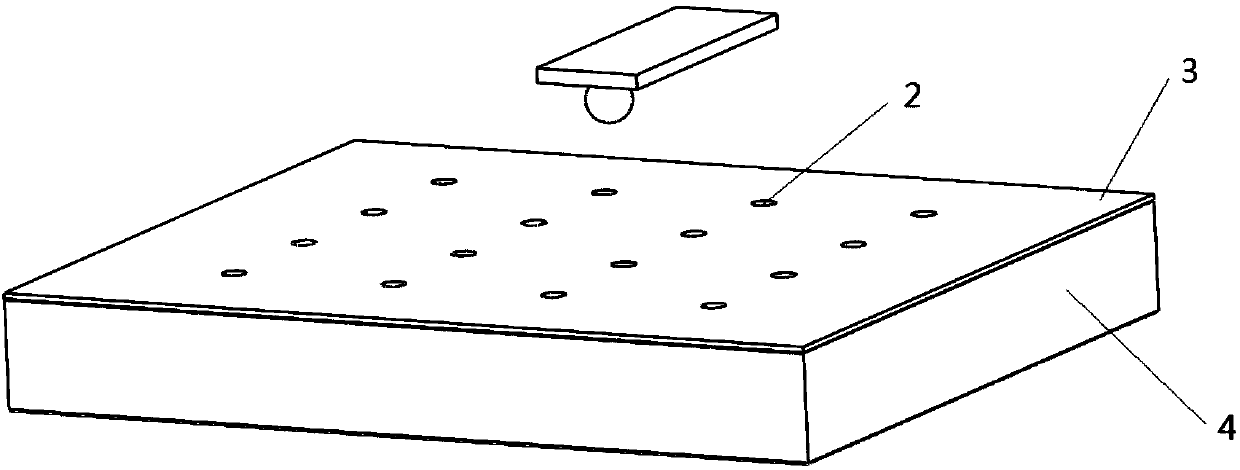
[0027] A. Coat a layer of wax film 3 on the slide glass 4, use multi-probe processing equipment to uniformly dot the wax film 3 and penetrate the wax film 3 to form evenly arranged spots on the wax film 3 Circular groove 2; see figure 1 .

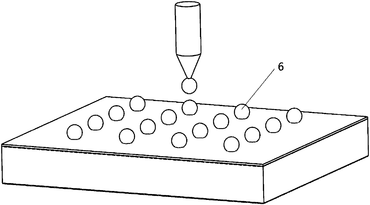
[0028] B, the same microsphere 6 of particle diameter is placed in each groove 2 on the wax film 3 one by one, and the diameter of described microsphere 6 is 5-10 times of the thickness of wax film 3; See figure 2 .

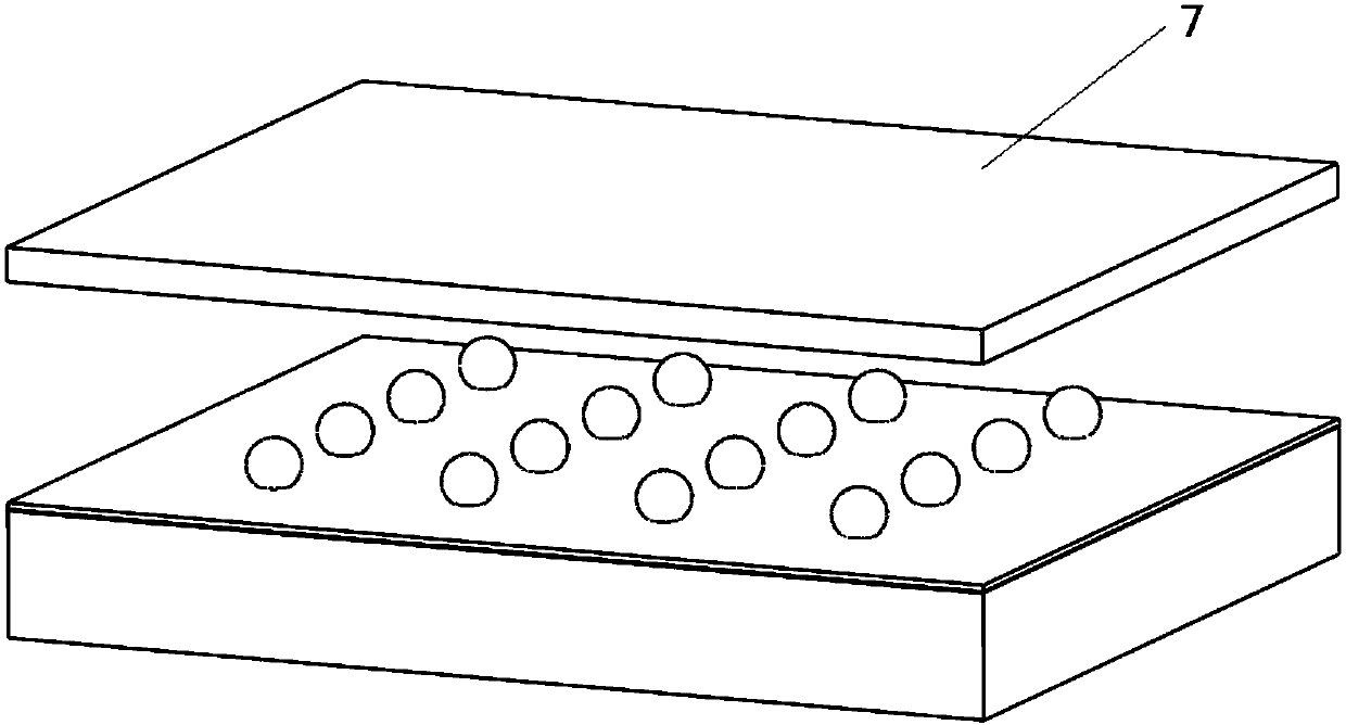
[0029] C. Press the microspheres 6 into the wax film 3 evenly with the glass slide 7, so that all the microspheres 6 are in contact with the slide glass 3; see image 3 .

[0030] D, the elastic material sheet 10 is bonded on the smooth pinpoint plate 8 by K-630 special fast-curing glue 9, and then coated wi...

Embodiment 2

[0035] The operation of this example is basically the same as that of Example 1, except that the microspheres are diamond microspheres.


PUM

PropertyMeasurementUnit
elastic modulusaaaaaaaaaa
thicknessaaaaaaaaaa

Abstract

A method for preparing a multi-point array for large-area micromachining with flatness self-compensation. The method is as follows: a layer of wax film (3) is coated on a glass slide (4), and a wax film (3) is formed on the wax film (3). Uniformly arranged grooves (2); microspheres (6) are placed in each groove (2) one by one, and then the microspheres (6) are pressed into the wax film with a glass slide (7) to make all the microspheres ( 6) All are in contact with the glass slide (3); the elastic material sheet (10) is bonded on the flat needle point plate (8), and then coated with a layer of ultraviolet glue (11). Press the UV glue surface of the pinpoint plate (8) flatly on the microsphere (6), and irradiate the UV glue with ultraviolet light at the same time to cure the UV glue, and the microsphere (6) is bonded on the pinpoint plate (8); finally, the wax sheet The film is melted, the slide glass (4) is taken away, and the residual wax on the surface of the microspheres (6) is washed off to obtain the product. The multi-point array processed by the method has good planarity, and the height of each needle point is consistent; and the preparation is simple, the cost is low, and the method is easy to implement.

Description

technical field [0001] The invention relates to a method for preparing a multi-point array for large-area micromachining. Background technique [0002] Micro-nano devices are widely used in advanced manufacturing, aerospace, military, biotechnology, computer and communication and other fields, and micro-nano processing technology, as one of the important processing technologies, is the basis for realizing the micro-nano functional structure of devices. With the help of micro-nano processing technology, people can design and prepare micro-nano materials or micro-nano structure devices and devices with excellent performance, develop methods and instruments for detecting and analyzing physical, chemical and biological phenomena at the nanoscale, and accurately characterize nanomaterials. Or the physical properties of nanostructures, exploring new laws and phenomena of material movement at the nanoscale. As one of the main technologies of micro-nano processing, scanning probe t...

Claims


Application Information

Patent Timeline
Patent Type & Authority Patents(China)
IPC IPC(8): B81C3/00
CPCB81C3/001
Inventor 钱林茂陈家良余丙军张超杰金晨宁汪洪波陈诚
Owner SOUTHWEST JIAOTONG UNIV
Learn More