
A method of manufacturing and manipulating a flexible micro-actuator for manipulating micro-nano particles

A technology of micro-nano particles and micro-actuators, applied in the direction of nanostructure manufacturing, nanotechnology, nanotechnology, etc., can solve the problems of difficult miniaturization and integration of optical paths, high cost, and long time, and achieve easy magnetic field drive and manufacturing process Simple, highly reliable results

Active Publication Date: 2017-04-19
XI AN JIAOTONG UNIV
View PDF3 Cites 0 Cited by
  • Summary
  • Abstract
  • Description
  • Claims
  • Application Information

AI Technical Summary

Problems solved by technology

[0003] At present, there are the following problems in the manipulation method of micro-nano particles: based on the surface acoustic wave acoustic control method, the preparation of micro-nano interdigitated electrodes is required, the process is complicated, and the cost is high; based on the atomic force microscopy method, since scanning and imaging cannot be performed simultaneously , resulting in low operating efficiency of the atomic force microscope, and it is difficult to realize large-scale batch nano-operation; the disadvantage of dielectrophoresis is that its electrodes need to be individually designed according to different manipulation purposes, and the preparation process of metal physical electrodes is complicated, time-consuming, and high-cost; optical tweezers technology Capable of manipulating nanoparticles with high precision
However, due to the limitations of light wave characteristics, it cannot manipulate objects in non-transparent media. At the same time, the thermal effect brought by the strong light field can easily cause photodamage to biological tissues, and the optical system structure is more complex and the optical path is not easy to miniaturize and integrate. Piezoelectric The transducer requires piezoelectric materials and high cost, which severely restricts the functional reliability of the devices required to manipulate micro-nanoparticles

Method used


Image

  • A method of manufacturing and manipulating a flexible micro-actuator for manipulating micro-nano particles
  • A method of manufacturing and manipulating a flexible micro-actuator for manipulating micro-nano particles
  • A method of manufacturing and manipulating a flexible micro-actuator for manipulating micro-nano particles

Examples


Embodiment 2

[0042] A method for manufacturing and manipulating a flexible micro-actuator for manipulating micro-nano particles, comprising the following steps:

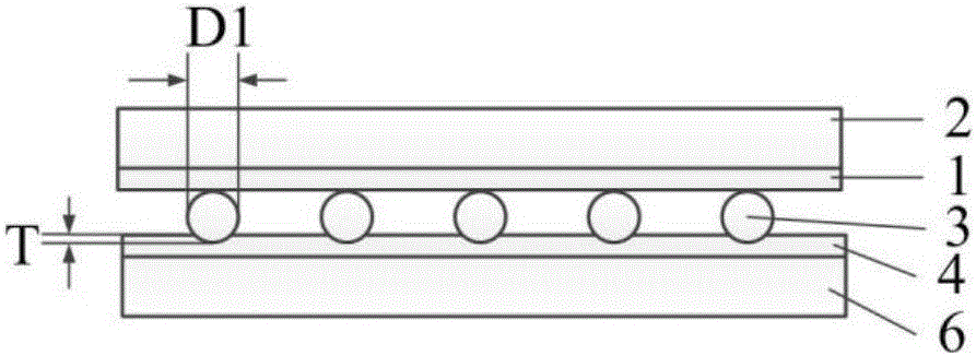
[0043] 1) First coat the hydrosol adhesive layer 1 on the surface of the substrate 2, then obtain a micro-nano patterned photoresist on the hydrosol adhesive layer 1 through a photolithography process; Micro-nanoparticles 3 are patterned, and then the photoresist is removed to obtain a patterned template of magnetic micro-nanoparticles 3, and the magnetic micro-nanoparticles 3 are iron powder with a particle size of D1=20 μm;

[0044] 2) Refer to figure 1 , coating the polymer 4 on the surface of the non-magnetic substrate 6, and then pre-heating the non-magnetic substrate 6, the pre-heating parameters: the temperature is 75°C, and the time is 6 minutes; then the magnetic micro-nano on the surface of the patterned template The particle 3 contacts and embeds the polymer 4, the embedding depth is T=10 μm, where T

Embodiment 3

[0054] A method for manufacturing and manipulating a flexible micro-actuator for manipulating micro-nano particles, comprising the following steps:

[0055] 1) First coat the hydrosol adhesive layer 1 on the surface of the substrate 2, then obtain a micro-nano patterned photoresist on the hydrosol adhesive layer 1 through a photolithography process; The micro-nanoparticles 3 are patterned, and then the photoresist is removed to obtain a patterned template of the magnetic micro-nanoparticles 3. The magnetic micro-nanoparticles 3 are cobalt powders with a particle size of D1=150 μm;

[0056] 2) Refer to figure 1 , coating the polymer 4 on the surface of the non-magnetic substrate 6, and then preheating the non-magnetic substrate 6, the pre-heating parameters: the temperature is 90°C, and the time is 2 minutes; then the magnetic micro-nanoparticles on the surface of the patterned template 3 contacting and embedding the polymer 4, the embedding depth is T=50 μm, where T


PUM

PropertyMeasurementUnit
particle diameteraaaaaaaaaa

Abstract

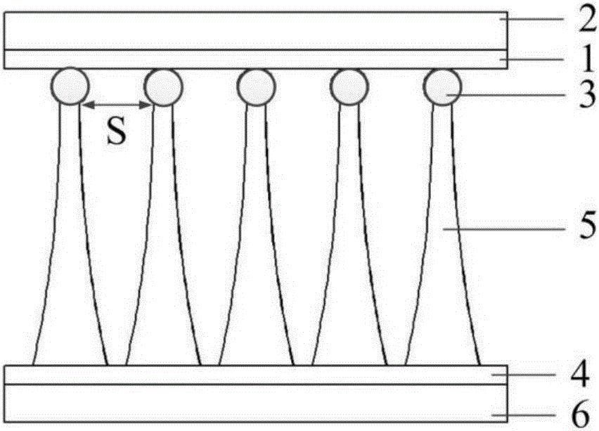
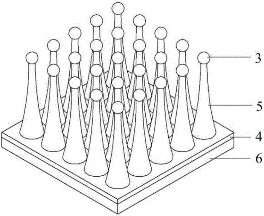
A manufacturing control method for a flexible micro-actuator that manipulates micro-nano particles. Firstly, a patterned template of magnetic micro-nano particles is made, and then the polymer is coated on the surface of a non-magnetic substrate, and the micro-nano particles on the surface of the patterned template are contacted and Embedding the polymer, pulling the patterned template, so that the polymer is stretched into a mushroom-shaped micro-nano pillar array, heating the patterned template to make the patterned magnetic micro-nano particles detach from the hydrosol adhesion layer, and the magnetic micro-nano particles with magnetic micro-nano particles on the top are obtained. The flexible mushroom-shaped micro-nano column array of particles, that is, the flexible micro-actuator, will need to be manipulated to drop the micro-nano particles onto the surface of the flexible mushroom-shaped micro-nano column array to regulate the position and horizontal / vertical movement of the magnet under the non-magnetic substrate The speed realizes the translation, grasping, and jumping manipulation of micro-nano particles, and the position and rotation speed of a pair of magnets on the non-magnetic substrate are adjusted to realize the rotation manipulation of micro-nano particles. The flexible driver of the present invention is simple to manufacture and has good controllability.

Description

technical field [0001] The invention belongs to the technical field of micro-nano manufacturing, and in particular relates to a method for manufacturing and controlling a flexible micro-actuator for manipulating micro-nano particles. Background technique [0002] At present, the methods for manipulating micro-nano particles mainly include: acoustic manipulation based on surface acoustic waves, atomic force microscopy, dielectrophoresis, photophotography, and piezoelectric transducers. Among them, the acoustic manipulation method based on surface acoustic waves mainly uses the particles in the sound field to produce reflection, refraction, absorption and other effects on the sound waves, so that the momentum carried by the sound field is exchanged between the sound waves and the particles, and then the particles are affected by the force to make them move. Be manipulated. Based on the atomic force microscope method, the manipulation of micro-nano particles is realized by mea...

Claims


Application Information

Patent Timeline
Patent Type & Authority Patents(China)
IPC IPC(8): B82B3/00B82Y40/00
CPCB82B3/0014B82B3/0076B82Y40/00
Inventor 蒋维涛刘红忠雷彪陈邦道史永胜尹磊
Owner XI AN JIAOTONG UNIV
Learn More