Inferior coal segmented-coupling gasifying device and gasifying method

A gasification device and low-quality coal technology, which is applied in the gasification process, granular/powder fuel gasification, combined combustion mitigation, etc. Strong adaptability, reduced energy consumption, and adjustable proportions

Active Publication Date: 2016-08-17
HARBIN INST OF TECH
View PDF9 Cites 16 Cited by
  • Summary
  • Abstract
  • Description
  • Claims
  • Application Information

AI Technical Summary

Problems solved by technology

[0012] The present invention aims to solve the problems of poor raw material adaptability of existing gasification devices, especially for low-quality coal, which is difficult to achieve economical, reliab

Method used


Image

  • Inferior coal segmented-coupling gasifying device and gasifying method
  • Inferior coal segmented-coupling gasifying device and gasifying method
  • Inferior coal segmented-coupling gasifying device and gasifying method

Examples


specific Embodiment approach 2

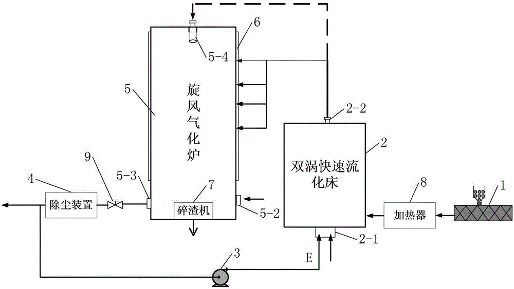
[0073]Specific implementation mode two: see figure 1 To illustrate this embodiment, the difference between this embodiment and the staged coupled gasification device for low-quality coal described in Embodiment 1 is that the optimum working temperature of the cyclone gasifier 5 is 1250°C.

[0074] In this embodiment, the equilibrium analysis shows that when municipal solid waste MSW is used as raw material, when the working temperature of the twin-vortex fast fluidized bed is 600°C, the optimum working temperature of the cyclone gasification furnace 5 is 1253°C, and the carbon conversion rate is as high as 98.9%, oxygen consumption is about 0.287, cold gas efficiency is about 82%.

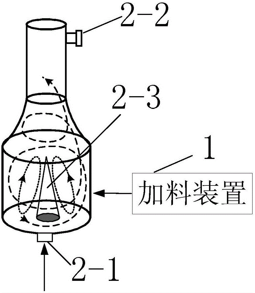
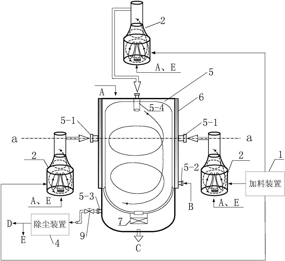
[0075] Specific implementation mode three: see figure 1 and figure 2 To illustrate this embodiment, the difference between this embodiment and the staged coupled gasification device for low-quality coal described in Embodiment 1 is that the twin-vortex fast fluidized bed 2 is divided into two pa...

specific Embodiment approach 9

[0091] Specific embodiment nine: adopt the gasification method realized by a kind of low-quality coal segmental coupling gasification device described in specific embodiment one, the specific process of this method is:

[0092] Step 1: Pass the inferior coal particles with a diameter less than 10mm through the feeding device 1 with N 2 or CO 2 Pressurize to 4MPa and send it into the twin-vortex fast fluidized bed 2, and at the same time feed the gasification agent tangentially through the No. 1 gasification agent inlet 2-1 at the bottom of the double-vortex fast fluidized bed 2, 2. The internal working temperature is within the range of 500°C to 980°C. The low-quality coal particles are pyrolyzed, and the raw coal gas generated spirals upward in the double-vortex fast fluidized bed 2 and is sprayed into the cyclone gasifier 5;

[0093] Step 2: Keep the working temperature of the cyclone gasifier 5 within the range of 1200°C to 1300°C, feed raw coal gas and gasification agent ...


PUM


Abstract

The invention discloses an interior coal segmented-coupling gasifying device and gasifying method and relates to the technical field of clean energy. The problems that existing gasifying device has low raw material adaptability and particularly is hard for realizing economical, reliable, clean and efficient gasification of interior coal and device amplification both are solved. The gasifying device comprises a charging device, a double-vortex fast fluidized bed, a circulating pump, a dust collector, a cyclone gasifier and a water cooling jacket, wherein the water cooling jacket wraps the outer wall of the cyclone gasifier; a slag crusher is arranged at the bottom of the cyclone gasifier; the slag crusher is used for crushing the slag falling to the bottom of the cyclone gasifier and discharging the slag out of the cyclone gasifier; the double-vortex fast fluidized bed is exclusively used for fluidizing, breaking and pyrolyzing a solid material at 500-980 DEG C to produce a raw gas; and the cyclone gasifier is exclusively used for performing carbon conversion of the raw gas introduced into the double-vortex fast fluidized bed at 1,200-1,300 DEG C to finally realize segmented coupling gasifying of inferior coal. The interior coal segmented-coupling gasifying device is mainly used for gasifying inferior coal.

Description

technical field [0001] The invention relates to the technical field of clean energy. Background technique [0002] Coal gasification technology is the foundation of modern coal chemical industry. It is the core technology for producing oil products through indirect coal liquefaction or producing methanol, synthetic oil, methane, etc. from syngas, and producing ethylene, propylene and other chemical products from methanol. . As the "leading" device in the coal chemical industry chain, the coal gasification device has the characteristics of large investment, high reliability requirements, and great impact on the economic benefits of the entire industrial chain. At present, there are many gasification technologies at home and abroad, and each technology has its own characteristics and specific applicable occasions. There are differences in their industrial application degree and reliability. The development of low-quality coal and new coal gasification technology suitable for...

Claims


Application Information

Patent Timeline
IPC IPC(8): C10J3/48C10J3/58C10J3/84
CPCY02E20/18C10J3/487C10J3/58C10J3/84C10J2300/093C10J2300/0956C10J2300/0959C10J2300/0966C10J2300/0969
Inventor 孙锐刑春礼朱文堃赵广播
Owner HARBIN INST OF TECH
Why Eureka
Try Eureka