Novel shielding tool for flywheel housing

A flywheel housing and tooling technology, applied in the direction of injection devices, etc., can solve the problems of easy deformation, contamination of the inner wall of the joint surface, uneven distribution of the fixing force of the cover, and achieve strong vibration and expansion ability, smooth paint surface without bulge, The effect of low processing cost

Inactive Publication Date: 2016-08-24
GUANGXI YUCHAI MASCH CO LTD
View PDF7 Cites 1 Cited by
  • Summary
  • Abstract
  • Description
  • Claims
  • Application Information

AI Technical Summary

Problems solved by technology

When this design is used for painting, the paint liquid is easy to accumulate on the peripheral part of the cover. In the process of engine circulation, this kind of cover is easy to be caused by vibration, local stress or uneven expansion when no screw is screwed or only a single screw is screwed. Partially loose and the shielding is not in place, so that the paint liquid penetrates downward under the action of gravity, and it is easy to remain on the axial joint surface of the shield cover and the flywheel housing, polluting the joint surface and the inner wall, and after long-term use, the hollowed out embedded part It is easy to deform, resulting in weak combination and short service life; in the case of fixing with multiple screws, because the distribution of screw positions is limited by the screw holes of the flywheel housing, the distribution of the fixing force of the cover is uneven, and local deformation is easy to occur after long-term use. As a result, the fit between the cover and the flywheel housing is not good, and the shielding effect is reduced, resulting in paint leakage and pollution.
At the same time, the butter is also very easy to contaminate the surrounding paint surface during the process of being dried and wiped by the engine, resulting in more paint leaks and cleaning positions.
Manual touch-up paint is completed at the station before leaving the factory. Manual touch-up paint not only affects the aesthetics of the product appearance, but also reduces the processing quality of our painting work, and also brings safety hazards of toxic gas pollution to the assembly workshop.

Method used


Image

  • Novel shielding tool for flywheel housing
  • Novel shielding tool for flywheel housing

Examples


specific Embodiment 1

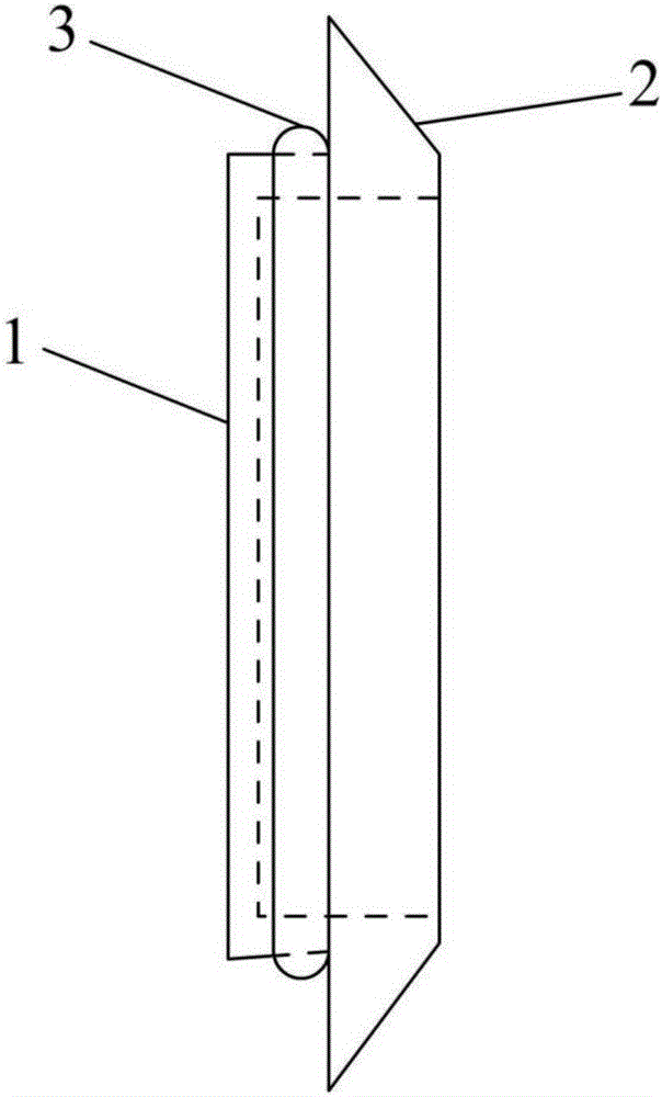
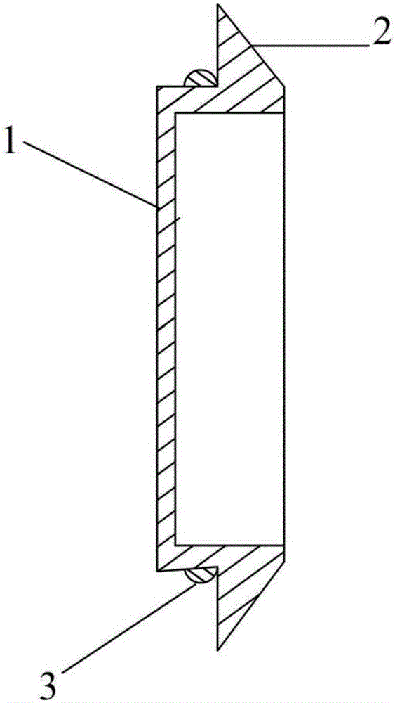
[0017] Such as Figure 1~2 As shown, a new type of flywheel shell shielding tooling includes a cover body, which is made of heat-resistant resin material with low expansion coefficient, and is recessed from the outside to the inside from the middle to form the inner convex body 1 in the middle and the peripheral part 2 structure; the diameter of the inner convex body 1 is 2mm smaller than the shielding cavity of the flywheel housing, which is beneficial to the disassembly and assembly of the cover; the peripheral part 2 is designed with a conical surface, and the conical surface is retracted, and the The tapered surface is smooth, and at the same time, after the cover is put into the flywheel housing, the top end of the peripheral part 2 is flush with the outer body surface of the joint of the flywheel housing. With this design, the diameter of the peripheral part gradually decreases backwards. It is conducive to the flow of paint liquid along the rear, and can effectively pre...

specific Embodiment 2

[0018] Such as Figure 1~2 As shown, a new type of flywheel shell shielding tooling includes a cover body, which is made of heat-resistant resin material with low expansion coefficient, and is recessed from the outside to the inside from the middle to form the inner convex body 1 in the middle and the peripheral part 2 structure; the diameter of the inner convex body 1 is 3mm smaller than the shielding inner cavity of the flywheel housing, which is beneficial to the disassembly and assembly of the cover; the peripheral part 2 is designed with a conical surface, and the conical surface is retracted, The tapered surface is smooth, and at the same time, after the cover is put into the flywheel housing, the top end of the peripheral part 2 is flush with the outer body surface of the joint of the flywheel housing. With this design, the diameter of the peripheral part gradually decreases backwards. It is beneficial for the paint liquid to flow along the rear, and can effectively pre...

specific Embodiment 3

[0019] Such as Figure 1~2 As shown, a new type of flywheel shell shielding tooling includes a cover body, which is made of heat-resistant resin material with low expansion coefficient, and is recessed from the outside to the inside from the middle to form the inner convex body 1 in the middle and the peripheral part 2 structure; the diameter of the inner convex body 1 is 4mm smaller than the shielding inner cavity of the flywheel housing, which is beneficial to the disassembly and assembly of the cover; the peripheral part 2 is designed with a conical surface, and the conical surface is retracted, and the The tapered surface is smooth, and at the same time, after the cover is put into the flywheel housing, the top end of the peripheral part 2 is flush with the outer body surface of the joint of the flywheel housing. With this design, the diameter of the peripheral part gradually decreases backwards. It is conducive to the flow of paint liquid along the rear, and can effective...


PUM


Abstract

The invention discloses a novel shielding tool for a flywheel housing. The novel shielding tool for the flywheel housing comprises a cover body, and the cover body is sunken from the middle to the exterior and forms an inner convex body in the middle and a periphery part; the size of the inner convex body corresponds to the size of a shielding cavity of the flywheel housing; the periphery part is designed to be of a conical surface, and the conical surface is of a retraction mode; after the flywheel housing is covered by the cover body, the top end of the periphery part is flush with the outer surface of the fit part of the flywheel housing. The novel shielding tool for the flywheel housing further comprises an elastic fastening ring, and the elastic fastening ring is combined at the intersection part of the inner convex body and the periphery part. The novel shielding tool for the flywheel housing has the advantages that the machining cost is low, the shielding effect is good in the paint spraying process, the operation is simple, the consumed time of processes is short, and the clearing workload and the painting make-up workload caused by missed painting can be greatly lowered.

Description

technical field [0001] The invention relates to the technical field of engine coating, in particular to a novel shielding tool for a flywheel housing. technical background [0002] The spray painting of the whole machine can improve the appearance quality of the product, control the uneven distribution of the spray paint color, reduce the number of painting during the assembly process, and improve production efficiency. The basic process of painting the whole engine is: shielding before cleaning - cleaning - drying - dismantling the shielding - shielding before painting - painting the whole machine - drying - dismantling the shielding. In the painting process of the complete engine machine, the three links of cleaning, painting and drying can be strictly controlled by mechanization. However, shielding and removal of shielding cannot be realized mechanically with an ideal cost input, and must be done manually. Therefore, designing a reasonable shielding tooling and shieldin...

Claims


Application Information

Patent Timeline
Patent Type & Authority Applications(China)
IPC IPC(8): B05B15/04
Inventor 朱荣刘显宏赵泽建杨献辉
Owner GUANGXI YUCHAI MASCH CO LTD
Why Eureka
Try Eureka