
Multifunctional combined grinding machine for valve

A multi-functional combination, grinding machine technology, applied in the direction of grinding machine, grinding bed, grinding machine parts, etc., can solve problems such as excessive product tolerance, waste of manpower, product tolerance exceeding the standard, etc., to meet the requirements of quality and precision, The effect of reducing the number of corrections and uniform product size

Pending Publication Date: 2016-08-24
SUZHOU TIANZHIJIAO PRECISION MACHINERY CO LTD
View PDF0 Cites 4 Cited by
  • Summary
  • Abstract
  • Description
  • Claims
  • Application Information

AI Technical Summary

Problems solved by technology

[0002] Nowadays, when producing the valves of automobile engines, it needs to go through seven machining processes, which are the outer circle of the disc, the chamfering of the outer circle of the disc, the 45° conical surface of the disc, the welding surface, the end face of the valve stem, the lock clip groove and the chamfering of the rod end face. Each of the above processes requires one or more targeted processing equipment to complete the processing, so several processing equipment are required to complete the processing of the valve of the automobile engine, because each processing equipment is independently operated Therefore, several operators are required to operate, which wastes manpower and increases the production cost of the enterprise, and the tolerance control of each process is different, which will lead to excessive product tolerance and uneven product size. In severe cases, the product tolerance exceeds the standard , resulting in waste products, reducing the yield of the product

Method used


Image

  • Multifunctional combined grinding machine for valve
  • Multifunctional combined grinding machine for valve
  • Multifunctional combined grinding machine for valve

Examples


Embodiment Construction

[0026] The following will clearly and completely describe the technical solutions in the embodiments of the present invention with reference to the accompanying drawings in the embodiments of the present invention. Obviously, the described embodiments are only some, not all, embodiments of the present invention. Based on the embodiments of the present invention, all other embodiments obtained by persons of ordinary skill in the art without creative efforts fall within the protection scope of the present invention.

[0027] The specific implementation manner of the present invention will be further described in detail below in conjunction with the schematic diagrams.

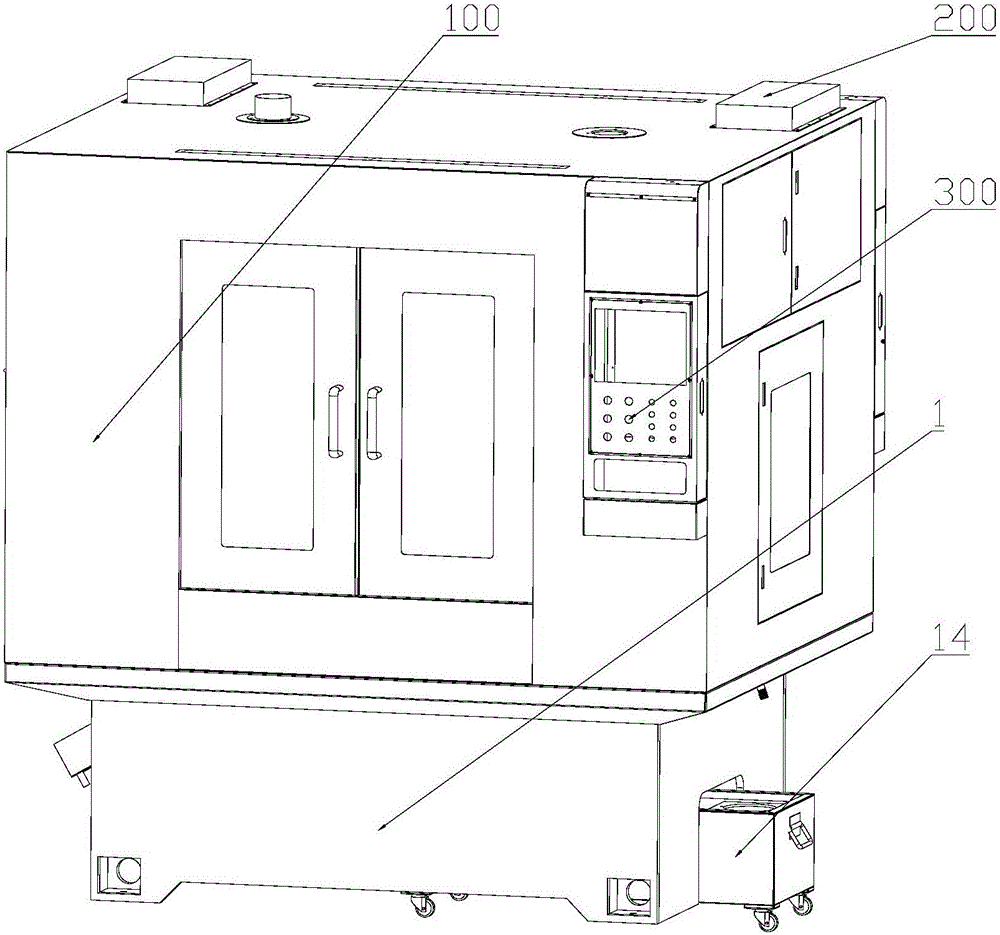
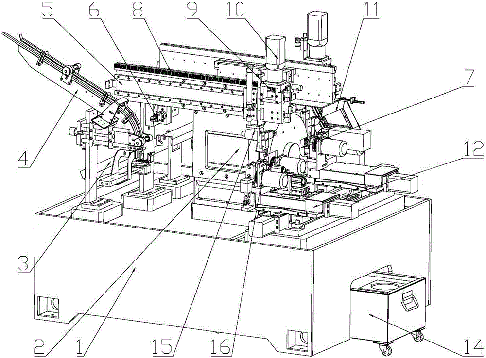
[0028] like figure 1 and figure 2 As shown, a valve multifunctional combination grinding machine includes a machine base 1 and a protective cover 100, the protective cover 100 is installed on the upper part of the machine base 1, a heat exchanger 200 is provided on the top of the protective cover 100, and a con...


PUM


Abstract

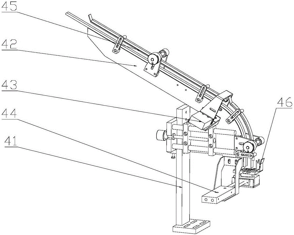
The invention discloses a valve multifunctional combined grinding machine, which comprises a machine base and a protective cover. The protective cover is installed on the upper part of the machine base. Heat exchangers and oil mist recovery devices are installed at the electrical cabinets on both sides of the top of the protective cover. There is a control panel at the top, and the two sides in the middle of the top of the machine base are respectively equipped with a material conveying assembly, an upper and lower arm assembly, a servo motor and a feeding slide assembly. There is a gear corresponding to the rack. The motorized spindle assembly is installed on the top of the machine base between the two conveying assemblies. The electric spindle assembly is equipped with a grinding wheel. The guide wheel assembly, the feed slide assembly on the other side of the top middle of the machine base is equipped with an oil-proof assembly on the back of the grinding wheel corresponding to the grinding wheel, and the station rotation assembly is installed on the material delivery assembly on the middle side of the top of the machine base. Seven processes Completed at one time, the tolerance control is unified, and the yield of the product is improved.

Description

technical field [0001] The invention relates to the technical field of production equipment for engine intake and exhaust valves, in particular to a valve multifunctional combination grinder for processing discs, rod end faces, lock clip grooves and rod end faces chamfering. Background technique [0002] Nowadays, when producing the valves of automobile engines, it needs to go through seven machining processes, which are the outer circle of the disc, the chamfering of the outer circle of the disc, the 45° conical surface of the disc, the welding surface, the end face of the valve stem, the lock clip groove and the chamfering of the rod end face. Each of the above processes requires one or more targeted processing equipment to complete the processing, so several processing equipment are required to complete the processing of the valve of the automobile engine, because each processing equipment is independently operated Therefore, several operators are required to operate, whi...

Claims


Application Information

Patent Timeline
IPC IPC(8): B24B27/00B24B55/12B24B41/00B24B47/12B24B41/02B24D7/18
CPCB24B27/00B24B41/005B24B41/02B24B47/12B24B55/12B24D7/18
Inventor 张长柏
Owner SUZHOU TIANZHIJIAO PRECISION MACHINERY CO LTD
Learn More