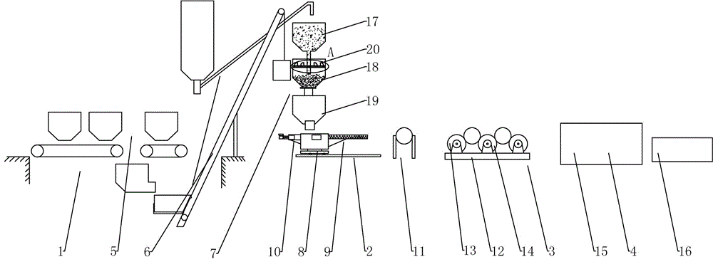
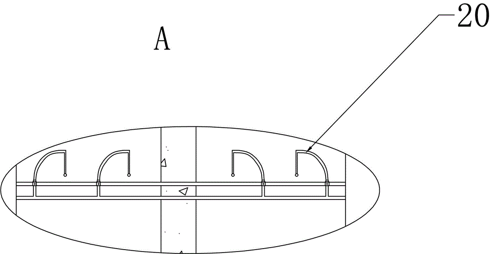
[0034] like figure 1 As shown, a steel fiber concrete pole production system includes concrete mixing and conveying equipment 1, feeding equipment 2, centrifugal equipment 3 and maintenance equipment 4, and the concrete mixing and conveying equipment 1 includes a weighing and conveying mechanism 5, and the weighing and conveying The mechanism 5 is connected with the multi-stage mixing mechanism 7 through the transmission mechanism 6, wherein the weighing conveying mechanism 5 includes a hopper for sand, cement and gravel respectively, and two weighing conveyor belts are arranged at the lower end of the hopper, and the materials fall into the Mix in the lower silo, and flow into the conveyor bucket from the inclined material port at one end, and the conveyor bucket is driven by the hoist to drive the wire rope to the multi-stage mixing and stirring mechanism; The upper two sides are respectively provided with a centrifugal feeding mechanism 9 and a secondary centrifugal feeding mechanism 10, and the centrifugal feeding mechanism 9 and the secondary centrifugal feeding mechanism 10 respectively feed twice centrifugally to the mold installed in the mold frame 11; The equipment 3 includes a base 12, on which two sets of fixed supporting wheels 13 and one set of movable supporting wheels 14 are arranged, and the three sets of supporting wheels all include a rotating shaft 41 and supporting wheels 42, wherein the movable supporting wheels 14 can be adjusted through a movable plate 43 Installed on the base 12, it can ensure that when the steel fiber concrete poles of different diameters are centrifuged, the force at the support point of the centrifugal wheel and the mold is appropriate, reducing the wear and noise between the centrifugal steel wheel and the mold, and improving the centrifugal wheel. service life. In addition, in order to prevent the impact of the steel supporting wheel and the steel mold in the centrifugal process of rotation to produce huge vibration and noise, an elastic damping plate 44 is provided at the lower end of the mounting seat of the rotating shaft 41; 15 is provided with a vertical mounting frame, the vertical mounting frame is made of channel steel, and the lower end is provided with a foot to provide a steam channel for steam circulation. By vertically installing the frame, the concrete structure is placed vertically for steam curing. Since the steam curing pools are installed and manufactured in underground pits, compared with horizontal placement, this can save a lot of space, and at the same time it is easy to install and improve Work efficiency: a hydration pool 16 is provided on one side of the steam curing pool 15, and the heat-cured concrete will lose more water and have a higher medium concentration, which will affect the hydration rate, and the hydration products will not be extended, making the strength of the concrete And compactness can not be significantly improved, so the hydration pool further provides conditions for cement hydration.
[0035]The multi-stage mixing and stirring mechanism 7 includes a primary mixing bucket 17, a secondary mixing bucket 18 and a tertiary mixing bucket 19, and the primary mixing bucket 17 carries out the primary mixing of cement, sand and stones, and the primary The discharge pipe of the mixing bucket 17 extends into the secondary mixing bucket 18, the upper part of the secondary mixing bucket 18 is provided with a mounting frame, and a plurality of fan-shaped nozzles 20 are installed on the mounting frame through an angle adjustment mechanism, and the angle adjustment The mechanism includes double sleeves 45, one of which is surrounded by a plurality of sockets 46, and is installed on the support frame through bolts and sockets 46; the other ring is provided with locking bolts 47, and is connected through the locking bolts. 47 realizes the locking of fan-shaped nozzle 20. The three-stage mixing bucket 19 is provided with a C-shaped stirring shaft 39, and the C-shaped stirring shaft 39 can realize the up-and-down stirring of the mixed material through the driving device to prevent the concrete from solidifying. The opening and closing mechanism, the opening and closing mechanism of the material opening includes a movable plate, which is fixedly connected with the piston rod of the cylinder, and is controlled by the control system to open and close. When mixing, by setting the primary mixing bucket, the primary mixing of additives such as cement, concrete, stones and water reducers can be carried out, because the discharge pipe of the primary mixing bucket extends into the secondary mixing bucket , the height of the raw material is controlled by the limiter in the secondary mixing bucket to avoid the blockage caused by the raw material and the water adding device above. Water is added proportionally through the secondary mixing bucket. Since the fan-shaped nozzles are distributed in multiple parts on the upper part of the secondary mixing bucket, water can be added evenly to avoid the mixture from clumping together and ensure that the raw materials are mixed quickly and evenly. In addition, the spray angle and installation position can be adjusted through the angle adjustment mechanism to meet the actual needs. In addition, it is also convenient for replacement and maintenance.
[0036] The walking rotation mechanism 8 includes a moving mechanism and a rotating mechanism, the moving mechanism includes a base 21, the lower end of the base 21 is arranged on the slide rail 23 through the walking wheels 22, and the upper end of the base 21 is controlled by the first servo motor 24 and the chain transmission mechanism 25 The traveling wheel 22 travels; the rotating mechanism includes a rotating shaft 26 driven to rotate by the second servo motor. During work, start the first servo motor, control the walking wheel to walk through the control system, and when reaching one side of the mold frame 11, the rotating shaft rotates so that the feeding device of the centrifugal feeding mechanism is facing the mold port on the mold frame.
[0037] The primary centrifugal feeding mechanism 9 includes a stirring mechanism 27 arranged on the base 21, the discharge port of the stirring mechanism 27 communicates with the feed port of the screw conveyor mechanism 28, and the central axis of the discharge pipe of the screw conveyor mechanism 28 is connected to the mold frame 11 The height of the mold on the board is consistent. When grouting, under the movement of the walking and rotating mechanism, firstly, the hopper at the upper end of the mixing mechanism receives the material; secondly, when it moves and rotates to a certain position, the mixing mechanism will stir the concrete through the outlet of the mixing mechanism at the same time. Entering the screw conveying mechanism, the screw conveying mechanism conveys to the cavity formed by the mold and the skeleton through the discharge pipe with an auger, and while conveying, the walking and rotating mechanism moves at a constant speed in the opposite direction of the feeding until one end is filled with concrete.
[0038] The secondary centrifugal feeding mechanism 10 includes a mounting seat 29 on which a pneumatic cylinder 30 is arranged. The pneumatic cylinder 30 communicates with a secondary stirring and feeding tank 31 , and a push plate 32 with a piston is arranged in the secondary feeding tank 31 . A stirring bucket is arranged above the secondary feeding tank 31, and a weighing device is arranged on the stirring bucket. Due to the first centrifugation, water and a small amount of slurry were thrown out, leaving gaps at both ends, and there was a problem of insufficient compactness, so feeding was required after the first centrifugation. After the concrete in the mold is centrifuged for the first time, under the movement of the walking and rotating mechanism, the mixing bucket of the second centrifugal feeding mechanism will receive the material; when it moves and rotates to a certain position, the pneumatic cylinder moves, and the piston rod of the cylinder moves forward. , the air pressure pushes the push plate to transport the concrete mixed with steel fiber to the end of the mold.
[0039] A plurality of steam nozzles 33 and temperature detectors 34 are equidistantly distributed from top to bottom on the side walls around the steam culture pool 15, and the steam nozzles 33 and temperature detectors 34 are connected with the control module 36 through the circuit drive module 35, Wherein, the circuit driving module includes a sensor conditioning circuit, an electric valve and an electric valve driving circuit. The control module is controlled by a single-chip microcomputer system. The steam culture pool is an insulation pool built underground, made of reinforced concrete, filled with insulation materials around it, and a cover made of thick steel plate on the top, 13 steam nozzles are evenly distributed around the pool, and the steam flowing into the pool is controlled by a regulating valve flow, and the temperature value in the pool is detected by the temperature detector, and the opening of the electric valve is controlled according to the process parameters to form a closed-loop control.
[0040] The bottom of the hydration pool 16 is provided with an installation frame 37 , and a plurality of automatic nozzle heads 38 are provided at the upper end. The pole is placed vertically through the installation frame, and the automatic nozzle head on it is used to spray water regularly for secondary water curing. After water curing, the calcium hydroxide and other substances in the concrete are dissolved to varying degrees. The calcium concentration is reduced, and the high-alkaline calcium silicate hydrate becomes a stronger low-alkaline calcium silicate hydrate, which significantly improves the strength and compactness of the concrete.
[0041] The feeding equipment 2 is divided into two groups and correspondingly arranged at the front and back of the mold frame 11 . In this way, materials can be fed from both ends of the mold frame at the same time, thereby improving work efficiency. In addition, due to the workability of steel fiber concrete, the grouting time is too long, the movement of steel fibers is blocked during centrifugation, and the phenomenon of steel fiber exposure after molding will be very serious. Therefore, feeding at both ends can not only increase the grouting speed but also improve the centrifugal quality.
[0042] A method for producing a steel fiber reinforced concrete pole, comprising the following steps:
[0043] 1. Preparation of concrete and steel skeleton: the screw conveyor transports various raw materials from the silo to the hopper filled with sand, cement and gravel, and the wet concrete material is weighed and mixed by the concrete mixing and conveying equipment 1. The mixing ratio of concrete wet material is: cement: 490.5~550.7 kg/m3; sand: 732.6~780.5 kg/m3; gravel: 1100.3~1423.4 kg/m3; water: 201.8~224.5 kg/m3 m; steel fiber: 2.6~4.1 kg/cubic meter; at the same time, according to the design requirements, the steel skeleton is made, and the prepared steel skeleton is put into the mold to adjust the positioning.
[0044] 2. Grouting: the control system starts the feeding equipment 2, so that the primary centrifugal feeding mechanism 9 completes the feeding, and through the movement positioning of the walking and rotating mechanism 8, the discharge pipe of the screw conveying mechanism 28 is continuously conveyed into the cavity formed by the mold and the skeleton Concrete is conveyed and retreated until the concrete grouting is finally completed.
[0045] 3. Stretching and centrifugation: firstly, prestress and stretch the steel skeleton, and the tension is controlled at 1300KN~1700KN, and then carry out centrifugal forming. The centrifugal forming adopts slow speed-medium speed-variable speed-high speed to increase step by step, from 1000 RPM~1300 RPM/min increased to 2500 RPM/min~2900 RPM/min.
[0046] 4. Feeding: A certain amount of concrete (about 5 kg-10 kg) is received in the hopper at the upper end of the secondary centrifugal feeding mechanism 10 for mixing; at the same time, the centrifuged mold is hoisted to the mold frame 11 through the door machine, and passed The secondary centrifugal feeding mechanism 10 adds concrete to both ends of the mold, followed by secondary centrifugation, and the centrifugal speed is controlled at 500 rpm to 1400 rpm. After the first steel fiber concrete pole was centrifuged, the concrete in the mold was centrifuged to remove part of the water and slurry, resulting in insufficient compactness and strength at both ends, which became the weak point of the strength of the entire pole. In addition, part of the water slurry remains in the center of the formed reinforced concrete structure, and the inner wall is rough and not smooth (the result of uneven dispersion of steel fibers). Through the second filling centrifugation, the strength of both ends of the concrete structure is greatly improved, the distribution density of the inner layer of steel fibers is increased, and the premature end of the pole or the inner wall of the concrete structure is avoided due to insufficient strength at both ends and insufficient density of lining steel fibers. phenomenon of cracking. At the same time, through two centrifuges, not only the distribution of steel fibers is more uniform, the overall strength of the pole (especially the bending strength) is improved, but also the corrosion and rust of the exposed steel fiber part is reduced, and the service life of the pole is improved.
[0047] 5. Concrete structure maintenance: put the concrete structure in the steam curing pool 15, heat up, keep constant and cool down according to the given process curve, and then pass in steam for manual maintenance. During the heating stage, the temperature is raised by 35°C per hour, and the constant temperature is maintained when it reaches 84°C state. In order to ensure that the temperature in the steam pool is basically balanced, the direction of the steam ejected from the nozzle is automatically adjusted to make the steam form a circular flow in the pool, and the steam valve is closed before the temperature is detected, so that the temperature in the pool reaches a basic balance, and then the data is collected. After completing the thermal curing, put it into the hydration tank 16 for regular water maintenance, and open the water outlet valve through the electromagnetic valve every half hour to sprinkle water on the concrete structure.