
Super-audio electromagnetic bar

An electromagnetic rod, super audio technology, applied in the direction of electric/magnetic/electromagnetic heating, electric heating devices, electrical components, etc., can solve the problems of rising ambient temperature, low service life, low electrothermal conversion rate, etc., to achieve fast heating speed, use Life extension effect

Active Publication Date: 2016-08-24
TIANJIN SAIJIN ENERGY SAVING SCI & TECH CO LTD
View PDF6 Cites 1 Cited by
  • Summary
  • Abstract
  • Description
  • Claims
  • Application Information

AI Technical Summary

Problems solved by technology

[0005] In the electromagnetic heating technology, similar domestic products are generally heated by electric heating coils, and the heat is transferred to the barrel through contact conduction. Dissipated into the air, there is a heat conduction loss and causes the ambient temperature to rise
[0006] In the electromagnetic heating technology, domestic similar products generally use straight iron-chromium-aluminum to generate heat due to resistance when passing current, which belongs to conduction heating. The disadvantage is that the electrothermal conversion rate is low.
[0007] In the electromagnetic heating technology, domestic similar products generally use iron-chromium-aluminum wire as the heat conduction wire, and the shell is made of iron or steel with relatively high carbon content. The disadvantages are that it is not resistant to oxidation, dry burning, and has a low service life. The heat generated by the iron-chromium-aluminum wire is conductive heating. When the water temperature exceeds 60°, calcium and magnesium ions will be precipitated and scale will be generated.

Method used


Image

  • Super-audio electromagnetic bar

Examples


Embodiment Construction

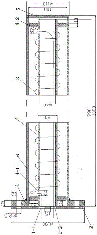
[0024] like figure 1 As shown, an ultrasonic frequency electromagnetic rod includes a flange 1, a flange 2, a coil 3, a ceramic tube 4, a bottom plate 5, and a stainless steel heating tube 6.

[0025] One end of the stainless steel heating tube 6 is welded with a bottom plate 5, the other end of the opening is welded with a flange 2, and several coils 3 are wound around the outside of the ceramic tube 4. The ceramic tube 4 is arranged in the stainless steel heating tube 6, and the joint at one end of the coil 3 passes through The upper outlet hole 4-1 of the ceramic tube 4 enters the ceramic tube 4 and extends out of the flange 1 hole I1-1 connected with the flange 2. The joint at the other end of the coil 3 passes through the lower outlet hole 4- of the ceramic tube 4. 2 Enter the ceramic tube 4 and extend out of the flange 1 hole II 1-2 connected with the flange 2.

[0026] The stainless steel heating tube 6 is made of 0Cr13 410s stainless steel tube with an outer diameter ...


PUM

PropertyMeasurementUnit
Outer diameteraaaaaaaaaa
Lengthaaaaaaaaaa
Outer diameteraaaaaaaaaa

Abstract

The invention relates to a super-audio electromagnetic bar. A bottom plate is welded at one end of a stainless steel heating tube, and a flange is welded outside an opening in the other end of the stainless steel heating tube; a coil winds around a ceramic tube by multiple circles at intervals; the ceramic tube is arranged inside the stainless steel heating tube; a joint at one end of the coil enters the ceramic tube via an upper coil outgoing hole in the ceramic tube and extends out of a hole I in a flange plate connected with the flange; and a joint at the other end of the coil enters the ceramic tube via a lower coil outgoing hole in the ceramic tube and extends out of a hole II in the flange plate connected with the flange. Problems of low electricity-heat transformation rates, disability of stepless regulation of output power, low maximum output power, disability of parching, short service life, possibility of production of scale and the like, which are not solved so far, of domestic like products are better solved. The electricity-heat transformation rate is higher than that of an external coil, electromagnetic wave shielding is realized, radiation and interference are avoided, water and electricity are separated, potential safety hazards are avoided, and the electromagnetic bar is simple in structure and can be widely applied to various electric heating devices.

Description

technical field [0001] The invention relates to a super audio frequency electromagnetic rod, which can be widely used in various types of electric heating equipment. Background technique [0002] In our life and production activities, heating is often used, and electric heating is the most common way. Due to its advantages of convenience and environmental protection, electric heating has gradually replaced the traditional heating methods such as firewood, charcoal and coal with serious environmental pollution and high safety hazards, and has become the mainstream heating technology. [0003] Among the electric heating methods on the market at this stage, resistance wire heating is more common. But resistance wire heating, its thermal efficiency is very low, mainly relying on contact conduction to transfer heat energy, only one surface contacts the part that needs to be heated, which causes a large part of the heat energy to be dissipated in the air. In addition, another di...

Claims


Application Information

Patent Timeline
IPC IPC(8): F22B1/28H05B6/36H05B6/16
CPCF22B1/281H05B6/16H05B6/367
Inventor 王德良
Owner TIANJIN SAIJIN ENERGY SAVING SCI & TECH CO LTD
Learn More