Envelope tracking power supply with broadband output

A technology for tracking power supply and envelope, which is used in output power conversion devices, DC power input conversion to DC power output, electrical components and other directions to reduce swing, improve system efficiency, and improve tracking bandwidth.

Inactive Publication Date: 2016-08-24
NANJING UNIV OF AERONAUTICS & ASTRONAUTICS
View PDF4 Cites 6 Cited by
  • Summary
  • Abstract
  • Description
  • Claims
  • Application Information

AI Technical Summary

Problems solved by technology

How to track the envelope signal with large swing and high speed changes poses a great challenge to the design of ET power supply

Method used


Image

  • Envelope tracking power supply with broadband output
  • Envelope tracking power supply with broadband output
  • Envelope tracking power supply with broadband output

Examples


example 1

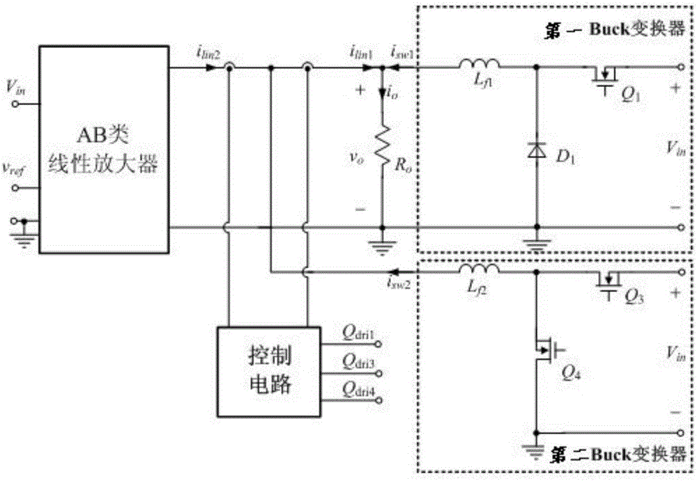
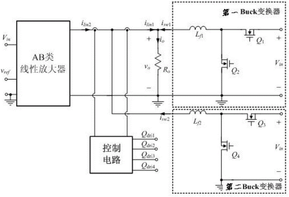
[0028] Figure 1 shows a schematic diagram of the system structure of the envelope tracking power supply with broadband output. The envelope tracking power supply with broadband output of the present invention includes two-way Buck converters, class AB linear amplifiers and a control circuit. The two-way Buck circuit is divided into a first Buck converter and a second Buck converter. The difference between Fig. 1(a) and Fig. 1(b) is that for the first Buck converter, from the perspective of simple structure and reliability, a control tube can use a diode, and from the perspective of improving the efficiency of the converter, the diode can also be replaced with switch tube, the other control tube is a switch tube; and because the first Buck converter in Figure 1(b) replaces the diode with a switch tube, so compared to Figure 1(a), the control circuit of Figure 1(b) needs Increase the control signal of the switch tube. The output of the class AB linear amplifier is connected in...

example 2

[0030] Accompanying drawing 3 (a) has provided the output characteristic of the hysteresis comparator, h is the hysteresis ring width of the hysteresis comparator, when the hysteresis comparator input signal v i (i=1,2) In the process of increasing from small to small within the hysteresis loop width, the hysteresis loop output S i (i=1,2) remains 1 until v i When reaching the hysteresis upper limit h / 2, S i becomes 0; when the hysteresis comparator input signal v i (i=1,2) During the process of decreasing from large to large within the hysteresis loop width, the hysteresis loop output S i (i=1,2) remains 0 until v i When the hysteresis lower limit -h / 2 is reached, S i becomes 1. In particular, accompanying drawing 3 (b) has given the output characteristics of the hysteresis comparator in the first current controller and the second current controller, wherein the dotted line represents the output characteristic of the hysteresis comparator of the first current controller,...

example 3

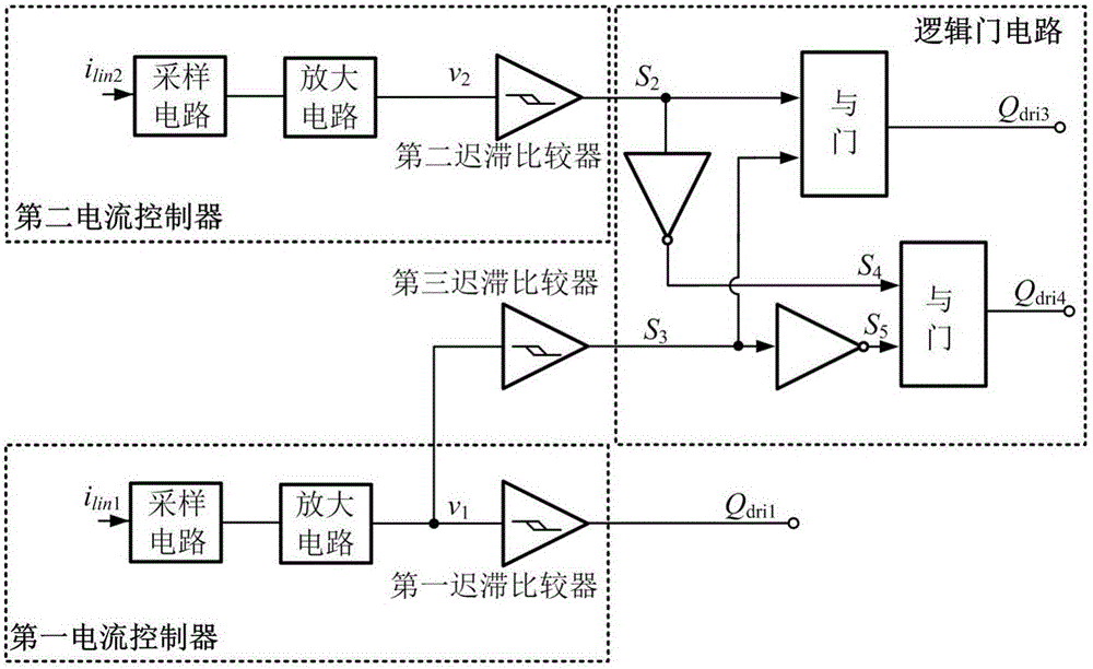
[0032]Accompanying drawing 2 (a) and accompanying drawing 2 (b) have given the control circuit of the envelope tracking power supply of broadband output, are made up of logic gate circuit, two-way current controller and the 3rd hysteresis comparator. Fig. 2 (a) has provided the corresponding control circuit diagram of Fig. 1 (a) circuit, and the first current controller comprises sampling circuit, amplifying circuit and first hysteresis comparator; The second current controller comprises sampling circuit, amplifying circuit and The second hysteresis comparator; the two sets of current controllers are connected through the third hysteresis comparator; wherein the first current controller samples the current i lin1 , through the amplifier circuit and the first hysteresis comparator to obtain the switching tube Q 1 The drive signal Q dri1 ; The second current controller samples the current i lin2 , the control signal S is obtained through the amplifying circuit and the second h...


PUM


Abstract

The invention provides an envelope tracking power supply with broadband output. The envelope tracking power supply comprises two paths of Buck converters, an AB-class linear amplifier and a control circuit, wherein the AB-class linear amplifier and the two paths of Buck converters are mutually connected in parallel; an output end of the AB-class linear amplifier is connected with a load in parallel; an output filter inductor of the first Buck converter is directly connected with an input end of the load; the output filter inductor of the second Buck converter is connected with a positive end of the output of the AB-class linear amplifier; the two paths of Buck converters and a negative end of the output of the AB-class linear amplifier are connected to the ground respectively; the control circuit comprises a logic gate circuit, two paths of current controllers and a third hysteresis comparator; each of the two paths of current controllers comprises a sampling circuit, an amplifying circuit and a hysteresis comparator; and the logic gate circuit comprises an AND gate and an NOT gate. The two paths of Buck converters are connected in parallel to provide a current to the load; the amplitude of oscillation of an output current of the linear amplifier is reduced; and the system efficiency is improved.

Description

technical field [0001] The invention relates to an envelope tracking power supply with broadband output, which is applied to the power supply of radio frequency power amplifiers of wireless communication equipment, and belongs to the category of communication and power conversion. Background technique [0002] With the development of economy and society, the requirements for data communication transmission rate are getting higher and higher. In order to increase the data transmission rate, modern wireless communication uses more efficient digital modulation techniques, such as quadrature phase shift keying, quadrature amplitude modulation, etc., to improve the efficiency of spectrum utilization. The application of these modulation techniques makes the envelope of the radio frequency signal (Radio Frequency, RF) change from the original constant form to the form with irregular amplitude changes. In the field of wireless communication, in order to ensure the linearity of powe...

Claims


Application Information

Patent Timeline
Patent Type & Authority Applications(China)
IPC IPC(8): H02M3/158
CPCH02M3/1584
Inventor 金茜阮新波冷阳王亚洲
Owner NANJING UNIV OF AERONAUTICS & ASTRONAUTICS
Why Eureka
Try Eureka