Control method for bidirectional quasi-Z-source inversion type motor driving system

A technology of a motor drive system and control method, which is applied in electronic commutation motor control, motor generator control, AC motor control, etc., can solve output voltage and current distortion, increase system electromagnetic noise, increase system torque ripple, etc. problem, to achieve the effect of reducing torque ripple

Active Publication Date: 2016-08-24
TONGJI UNIV
View PDF6 Cites 18 Cited by
  • Summary
  • Abstract
  • Description
  • Claims
  • Application Information

AI Technical Summary

Problems solved by technology

[0003] 1. The bus voltage of the voltage-type inverter is the output voltage of the battery, which is limited by the battery voltage. When the car is climbing and accelerating, the voltage will drop when the battery is insufficient, resulting in insufficient output power of the motor. In order to improve Due to the soft characteristics of battery output, in fuel cell vehicles and electric commercial vehicles, a non-isolated BOOST circuit is usually added to the output end of the battery. After the BOOST circuit increases the voltage, it supplies the three-phase bridge inverter to drive the motor. The first-stage DC/DC inverter is a two-stage circuit, and the transmission efficiency of the system as a whole is low after two-stage conversion
[0004] 2. The upper and lower bridge arms of the tr

Method used


Image

  • Control method for bidirectional quasi-Z-source inversion type motor driving system
  • Control method for bidirectional quasi-Z-source inversion type motor driving system
  • Control method for bidirectional quasi-Z-source inversion type motor driving system

Examples


Embodiment Construction

[0053] The present invention will be described in detail below in conjunction with the accompanying drawings and specific embodiments. This embodiment is carried out on the premise of the technical solution of the present invention, and detailed implementation and specific operation process are given, but the protection scope of the present invention is not limited to the following embodiments.

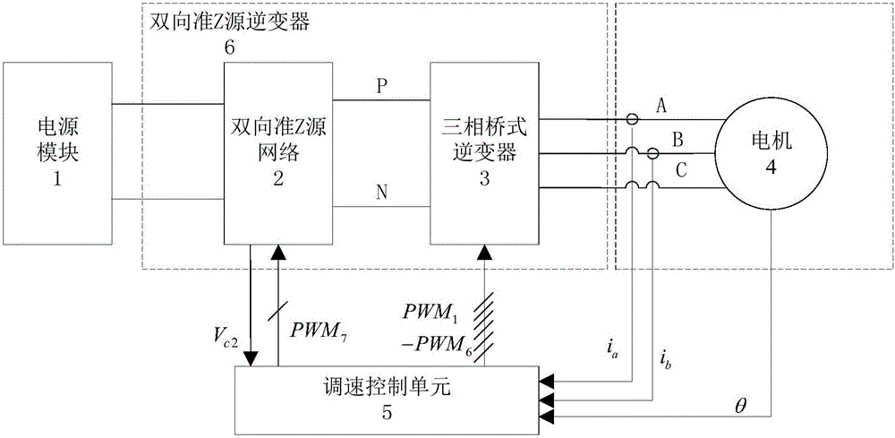
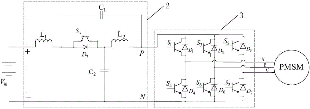
[0054] Such as figure 1 and figure 2 As shown, a control method of a bidirectional quasi-Z source inverter motor drive system, the bidirectional quasi-Z source inverter motor drive system includes a power module 1 connected in sequence, a bidirectional quasi-Z source front-stage passive network 2, a three-phase The bridge inverter 3 and the motor 4 have a specific structure as follows:

[0055] The power module 1 uses a DC battery pack, and the motor 4 can be a permanent magnet synchronous motor, an asynchronous motor, a DC brushless motor, etc. This example uses a permanent magnet...


PUM


Abstract

The invention relates to a control method for a bidirectional quasi-Z-source inversion type motor driving system. The control method comprises the following steps of collecting the voltage of a capacitor C2 and the current of a permanent magnet synchronous motor; obtaining voltage components of a d axis and a q axis; obtaining a direct-connection duty ratio; carrying out an SVPWM (space vector pulse width modulation) algorithm by inserting the direct-connection duty ratio according to the voltage components of the d axis and the q axis and the direct-through duty ratio to obtain six paths of PWM control signals for controlling the on and off of three-phase bridge arms of a three-phase bridge type inverter; and carrying out logic calculation on the six paths of PWM control signals to output a PWM control signal for controlling the on and off of an IGBT switch tube S7. Compared with the prior art, the average direct-connection duty ratio and the capacitor voltage closed loop control closed loop policy are added to the conventional SVPWM control method, so that the direct current side voltage has the voltage boosting capability; and on the basis, the power switch S7 which is complementary with the direct-connection state is further designed, so that the bidirectional flow of energy can be realized.

Description

technical field [0001] The invention relates to the field of automobile motor and control technology, in particular to a control method of a bidirectional quasi-Z source inverter motor drive system. Background technique [0002] In the traditional electric drive system, the inverter is a voltage type inverter, which has the following disadvantages: [0003] 1. The bus voltage of the voltage-type inverter is the output voltage of the battery, which is limited by the battery voltage. When the car is climbing and accelerating, the voltage will drop when the battery is insufficient, resulting in insufficient output power of the motor. In order to improve Due to the soft characteristics of battery output, a non-isolated BOOST circuit is usually added to the output end of the battery in fuel cell vehicles and electric commercial vehicles. After the BOOST circuit increases the voltage, it is supplied to the three-phase bridge inverter to drive the motor. The level DC / DC inverter i...

Claims


Application Information

Patent Timeline
IPC IPC(8): H02P21/05H02P27/12H02M7/797
CPCH02M7/797H02P21/05H02P27/12
Inventor 康劲松王硕武松林蒋飞
Owner TONGJI UNIV
Why Eureka
Try Eureka