Urine multi-index detection microfluidic device and preparation method thereof

A microfluidic device and multi-indicator technology, applied in chemical instruments and methods, biological testing, material inspection products, etc., can solve the problems of high cost, difficult to achieve fast and low-cost preparation, cumbersome procedures, etc., and achieve high accuracy , good preservation effect, and the effect of simplifying the operation steps

Inactive Publication Date: 2016-09-07
SHANGHAI JIAO TONG UNIV
View PDF3 Cites 7 Cited by
  • Summary
  • Abstract
  • Description
  • Claims
  • Application Information

AI Technical Summary

Problems solved by technology

Traditional microfluidic chips are mainly realized by photolithography, which requires a series of steps such as cleaning, spin coating, and ultraviolet exposure on silicon wafers. The process is cumbersome and costly. Therefore, it is difficult to achieve rapid and low-cost preparation.

Method used


Image

  • Urine multi-index detection microfluidic device and preparation method thereof
  • Urine multi-index detection microfluidic device and preparation method thereof
  • Urine multi-index detection microfluidic device and preparation method thereof

Examples


Embodiment 1

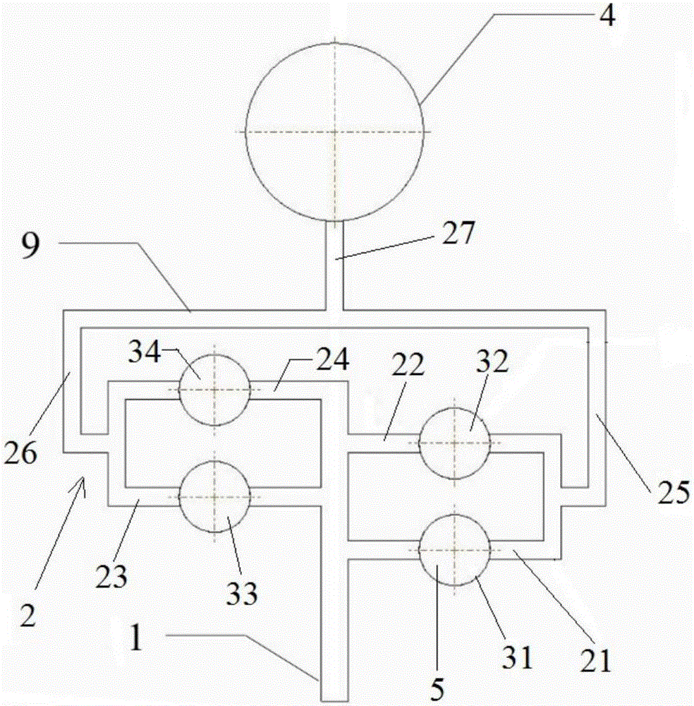
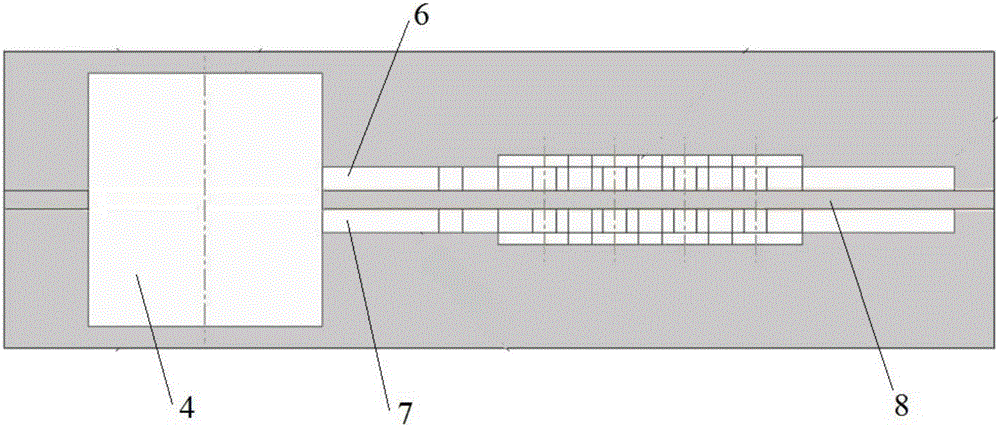
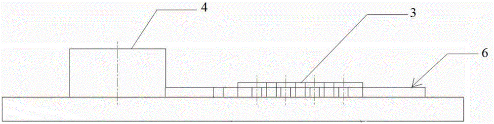
[0046] This embodiment relates to a urine multi-index detection microfluidic device, such as Figure 1-5 As shown, it includes an upper channel 6, a lower channel 7, and an intermediate layer 8. The device also includes 8 reaction areas 3, which can simultaneously detect 8 indicators, of which 4 are distributed in the upper channel 6, and the other 4 are distributed in the lower layer. Pathway 7. The specific example diagram and usage diagram are as follows Figure 4 and Figure 5 shown.

[0047]Take layer path 6 as an example, see figure 1 , the sampling port is located in the middle of the upstream edge of the entire device, and the sampling channel 1 is located downstream of the sampling port, approximately on the longitudinal centerline of the entire device. The four first flow channels 21 , 22 , 23 and 24 are located on both sides of the sampling channel 1 , two on each side. The first flow passages 21 and 22 are arranged in parallel, the first flow passages 23 and 2...

Embodiment 2

[0058] This embodiment relates to another urine multi-index detection microfluidic device, which includes a first unit composed of a first upper layer passage, a first lower layer passage and a first middle layer, and a second upper layer passage, a second lower layer A second unit consisting of a via and a second intermediate layer. The first unit and the second unit are relatively independent, and their internal structures are similar to those in Embodiment 1, respectively. The cladding layer wraps the outside of the two units to isolate the first unit and the second unit from the external environment, and meanwhile the cladding layer itself also forms a bag-shaped container.

[0059] Inside the cladding layer, near the inlets of the sampling channels of the two units, a sampling port that can be pulled apart to form a funnel shape is provided, and a part of the bottom of the sampling port communicates with the channel inlets of the two units, so that A part of the liquid c...

Embodiment 3

[0062] This embodiment relates to a method for preparing a urine multi-indicator detection microfluidic device as in Embodiment 1, specifically as follows:

[0063] 1. Design of 3D mold: use 3D drawing software to design the channel model, wherein, the sampling channel 1 is 1.5 mm wide and 1 mm high, the flow channel 2 is 1 mm wide and 1 mm high, and the reaction zone diameter is 4 mm and 1.5 mm high. mm, the liquid collection chamber 4 has a diameter of 10mm and a height of 5mm.

[0064] 2. Printing mold: Using fused deposition accumulation technology and hot-melt plastics, print on a substrate to form the aforementioned 3D mold.

[0065] 3. Pouring: Mix PDMS (polydimethylsiloxane) and curing agent at a weight ratio of 10:1, stir and mix well, pour on the mold, and place it in an oven at 70°C for more than 8 hours to cure. Wherein, the curing agent is a commonly used curing agent in the field, including sulfur, selenium, tellurium, sulfur-containing compounds, metal oxides, ...


PUM


Abstract

The invention discloses a urine multi-index detection microfluidic device. The device includes the following parts: an inlet channel, which is located in the upstream of the device; two or more flow channels, which are communicated with the inlet channel and located in the downstream of the inlet channel; a reaction zone, which is located in the flow channel, and includes analysis test paper; a liquid collection chamber, which is in the downstream of the reaction zone and communicated with the downstream end of the flow channel. An upper passageway formed by the inlet channel, the flow channel, the reaction zone and the liquid collection chamber comprises a first passageway layer and a middle layer. A plurality of layers can operate to detect multiple indexes; and the processes of urine taking, reaction, detection and analysis can be completed in a short time, so as to greatly simplify the operation steps, save time and increase the efficiency. In addition, the invention also discloses a preparation method of the device. The method adopts a piece of three-dimensional drawing software to design a passageway model and combines with the three-dimensional printing passageway model, so as to prepare the device in a rapid and cost-saving way.

Description

technical field [0001] The invention belongs to the technical field of biological detection, and relates to a urine detection device, in particular to a urine multi-index detection microfluidic device. Background technique [0002] Routine urine examination is one of the commonly used clinical medical examination items at present, which can reflect the severity of diseases in the kidney and urinary system. It has an important reference value for the diagnosis of certain systemic diseases and other diseases that affect urine changes, such as diabetes, blood diseases, liver and gallbladder diseases, and epidemic hemorrhagic fever. In addition, the urine test also has an important reference value for the treatment effect and prognosis of some systemic diseases. [0003] With the improvement of people's living standards, the incidence of diseases such as diabetes and gout has increased significantly, seriously endangering human health. At present, in most cases, urinalysis tes...

Claims


Application Information

Patent Timeline
Patent Type & Authority Applications(China)
IPC IPC(8): B01L3/00G01N33/50
CPCB01L3/502707B01L2200/10G01N33/50
Inventor 刘硕鹏丁显廷陈守慧苏文琼李宗霖
Owner SHANGHAI JIAO TONG UNIV
Why Eureka
Try Eureka