Thin-layer reactive powder concrete vibrating and levelling method and system

A kind of active powder and concrete technology, which is applied in the direction of construction, building structure, and building material processing, etc., can solve the problems of low efficiency, inability to realize automatic continuous operation, low flatness, etc., and achieve efficiency improvement, flatness improvement, leveling good effect

Active Publication Date: 2016-09-07
HUNAN ZHONGLU HUACHENG BRIDGE TECH CO LTD
View PDF5 Cites 5 Cited by
  • Summary
  • Abstract
  • Description
  • Claims
  • Application Information

AI Technical Summary

Problems solved by technology

Ordinary high-frequency vibrating and leveling devices require manual operation, which is inefficient and has low flatness, and cannot realize automatic continuous operation

Method used


Image

  • Thin-layer reactive powder concrete vibrating and levelling method and system
  • Thin-layer reactive powder concrete vibrating and levelling method and system
  • Thin-layer reactive powder concrete vibrating and levelling method and system

Examples


Embodiment 1

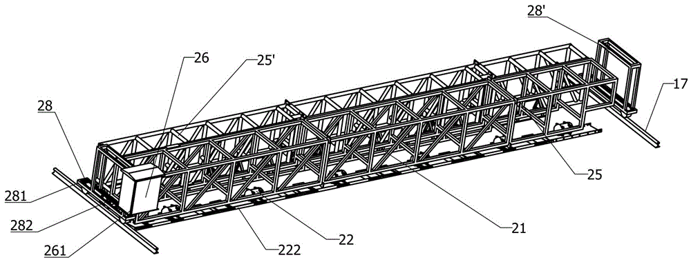
[0035] Embodiment 1, the present invention includes a vibrating truss 25, a suspended high-frequency vibrating device 22, a suspended leveling device 21, a vibrating and leveling parallel walking device 28, and a vibrating and leveling intelligent control device 26, wherein the suspended high-frequency vibrating device 22 Suspended below the advancing direction of the vibrating truss 25, the suspended leveling device 21 is suspended below the advancing direction of the vibrating truss 25; The leveling intelligent control device 26 is installed on the sides of the two ends of the vibrating truss 25, and the entire vibrating and leveling system is installed on the longitudinal rail 17. When the system is working, the vibrating and leveling parallel traveling device 28 is first started to move forward. The suspended high-frequency vibrating device When the vibrating plate 222 of 22 touches the active powder concrete, the high-frequency vibration motor 221 is turned on, and the lev...

Embodiment 2

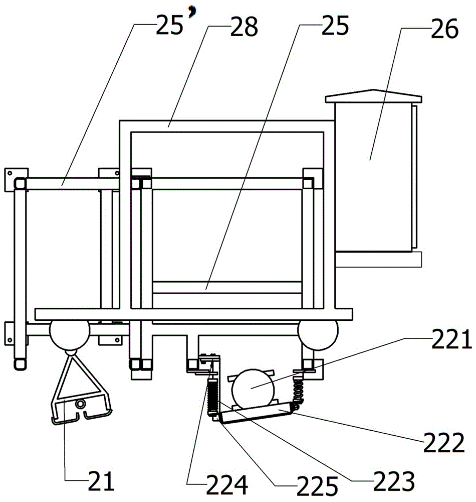
[0036] Embodiment 2, the suspended high-frequency vibrating device 22 of the present invention includes a vibrating truss 25, a high-frequency vibrating motor 221, a vibrating plate 222, an elastic suspension device 223, and a vibrating plate bevel adjustment device 224, wherein each vibrating plate 222 is Install a high-frequency vibration motor 221, the vibrating plate 222 is at an angle of 1°~70° to the horizontal, the elastic suspension device 223 is installed under the vibrating truss 25, and a vibration damping device 225 is arranged between the elastic suspension device 223 and the vibrating plate 222 . The angle between the vibrating plate 222 and the horizontal direction is adjusted by the vibrating plate oblique angle adjustment device 224 . The vibrating truss 25 drives the vibrating plate 222 to realize the function of moving up and down. refer to Figure 1 to Figure 7 , and the rest are the same as the combination of any of the above embodiments or two or more e...

Embodiment 3

[0037] Embodiment 3, the vibrating plate 222 of the suspended high-frequency vibrating device 22 of the present invention can be formed by connecting more than one plate, and a group of plate chains with a length of 0.3 to 50 m can complete the vibrating operation once in this wide section range; the vibrating plate Set 20~100mm high coaming panels around 222, set one hanging hook on the front coaming panel, set two hanging hooks on the rear coaming panel, and connect the hooks and the coaming panel with hinged hole bolts. refer to Figure 1 to Figure 7 , and the rest are the same as the combination of any of the above embodiments or two or more embodiments.


PUM


Abstract

The invention relates to a thin-layer reactive powder concrete vibrating and levelling method and system, mainly solving the technical problem that reactive powder concrete needs to be vibrated and levelled for multiple times and the like. According to the technical scheme, the system comprises a vibrating truss (25), suspension type high-frequency vibrating devices (22), suspension type levelling devices (21), a vibrating and levelling travelling device (28) and a smart vibrating and levelling control unit (26), and the suspension type high-frequency vibrating devices (22) and the suspension type levelling devices (21) are hung below the vibrating truss (25); the vibrating truss (25) is mounted on the vibrating and levelling travelling device (28), the smart vibrating and levelling control unit (26) is mounted on the side face of the end of the vibrating truss (25), and the whole vibrating and levelling system is mounted on longitudinal rails (17). Due to the fact that manual operation is not required, efficiency and levelness are improved greatly, and automatic and continuous operation is realized. The method and system is mainly applied to the fields of reactive powder concrete production and construction and the like.

Description

technical field [0001] The invention relates to a concrete paving machine, in particular to a method and system for vibrating and leveling thin-layer active powder concrete. Background technique [0002] At present, due to the shortcomings of ordinary concrete such as low tensile strength, poor toughness, and crack development after cracking, the premature deterioration of concrete structures cannot continue to be used, and the durability and service life of important concrete structures have also been greatly reduced. . In order to overcome these shortcomings of concrete, ultra-high toughness cement-based composite (ECC) was proposed to be applied to concrete. Optimized, and add 2%~3.5% volume ratio of fiber. The concrete made of this kind of ultra-high toughness cement-based composite material can significantly improve the tensile strength and shear resistance of concrete. Therefore, the good toughness of this kind of concrete can effectively control the development of c...

Claims


Application Information

Patent Timeline
Patent Type & Authority Applications(China)
IPC IPC(8): E04G21/06E04G21/10
CPCE04G21/066E04G21/10
Inventor 张法彭力军李沧万国强谢方生谭志许友康大桥
Owner HUNAN ZHONGLU HUACHENG BRIDGE TECH CO LTD
Why Eureka
Try Eureka