Cavitation prevention slurry pump

A slurry pump and anti-cavitation technology, which is applied in the direction of pumps, pump components, non-displacement pumps, etc., can solve problems such as dynamic balance damage, life of flow-passing parts that cannot meet the use requirements, and product competitiveness decline, etc., to achieve easy The effect of demoulding

Inactive Publication Date: 2016-09-07
GUANGZHOU TOTALL MATERIAL TECH CO LTD
View PDF6 Cites 9 Cited by
  • Summary
  • Abstract
  • Description
  • Claims
  • Application Information

AI Technical Summary

Problems solved by technology

Common slurry pumps are usually made of wear-resistant alloys such as Cr26 and Cr15Mo3. They can be used normally when transporting some low-concentration solid-liquid two-phase flow media, but they can be used normally when transporting high-concentration, especially solid-liquid two-phase flow. When it is above 55%, ordinary slurry pumps show the following problems: 1. The wear problem is prominent, and the life of the flow-passing parts often cannot meet the service requirements
2. The anti-cavitation performance is poor. This is because as the concentration of the two-phase flow increases, the fluidity of the medium continues to decrease, and the NPSH is much smaller than that of clean water, resulting in cavitation when the flow rate of the pump is much lower than the calibration value. Not only the wetted parts are easily damaged, but the performance of th...

Method used


Image

  • Cavitation prevention slurry pump
  • Cavitation prevention slurry pump
  • Cavitation prevention slurry pump

Examples


Embodiment 1

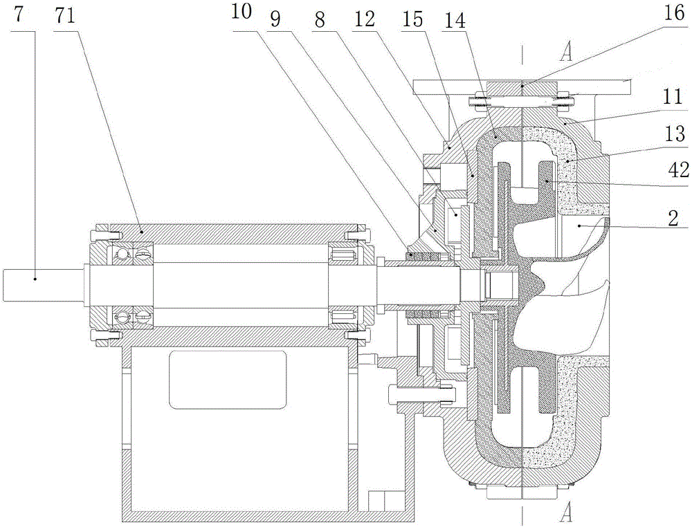
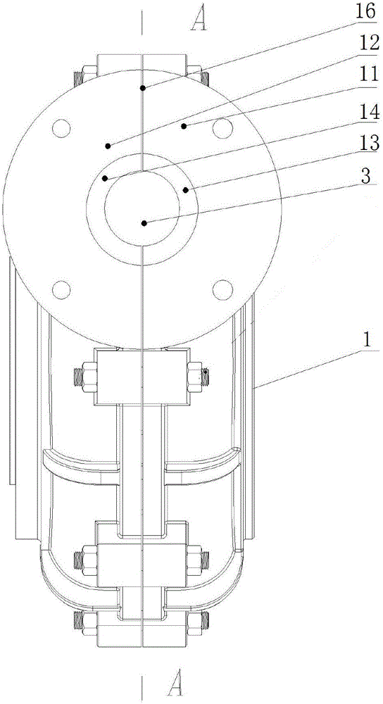
[0037] like Figure 1-6 as well as Figure 11 As shown, an anti-cavitation slurry pump includes a pump body 1, the pump body 1 is provided with a suction port 2 and a discharge port 3, and the pump body 1 is provided with an impeller 4, and the impeller 4 is provided with a centrifugal main blade 5 and an axial flow induction blade 6, the induction blade 6 extends to the position of the suction inlet 2, and the main blade 5 and the induction blade 6 are connected. Preferably, both the induction blade 6 and the main blade 5 are 4 pieces, of course, in the production application, 3 or 5 pieces of the induction blade 6 and the main blade 5 can also be provided respectively according to the production situation.

[0038] In practical applications, the centrifugal main blade 5 and the axial flow induction blade 6 can effectively increase the NPSH of the pump, or reduce the intensity of cavitation.

[0039]In order to further increase the NPSH of the pump, the cross-sectional area...

Embodiment 2

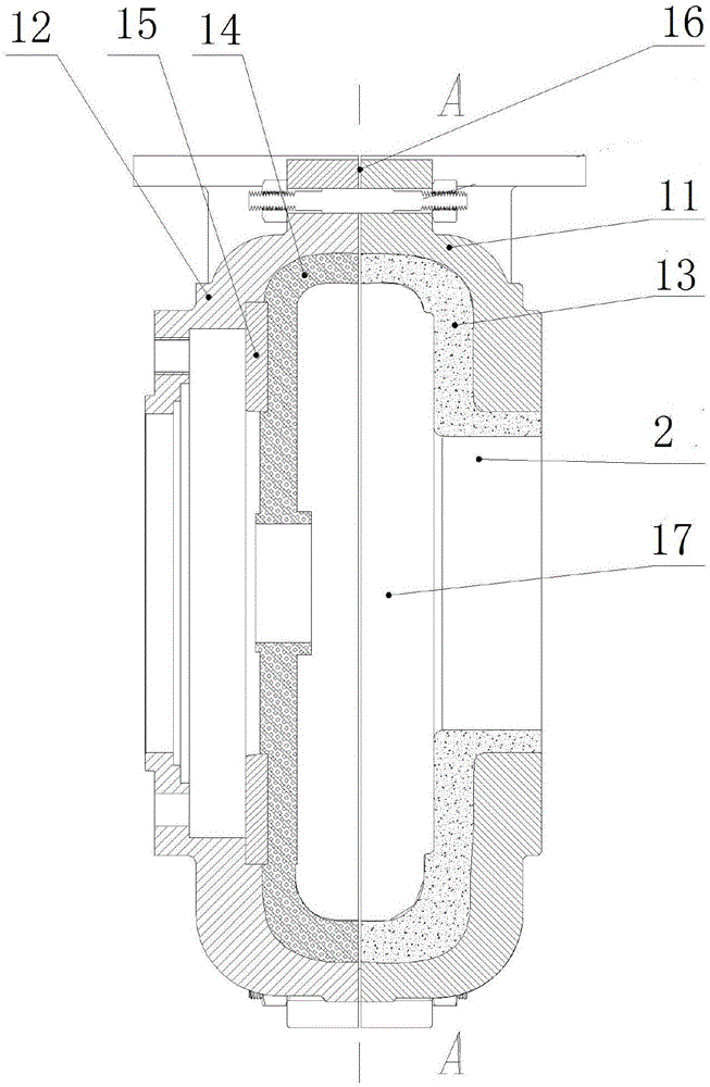
[0049] Such as Figure 7-10 as well as Figure 12 As shown, it is substantially the same as Embodiment 1, the difference is that the impeller 4 is a semi-open impeller, the impeller 4 includes a rear cover 41, the main blade 5 is arranged on the rear cover 41 and It is connected to the induction vane 6 through a smooth transition zone 51 .

[0050] The main blade 5 is a mixed flow blade, and the induced blade 6 is an axial flow blade.

[0051] The diameter of the suction port 2 is 300 mm, the diameter of the discharge port 3 is 150 mm, and the cross-sectional area of ​​the suction port 2 is four times the cross-sectional area of ​​the discharge port 3 .

[0052] The main components of the composite wear-resistant material are 82% (weight) of aluminum oxide and 15% (weight) of vinyl resin.


PUM


Abstract

The invention discloses a cavitation prevention slurry pump. The cavitation prevention slurry pump comprises a pump body. The pump body is provided with a suck-in opening and a discharge opening. An impeller is arranged in the pump body and provided with main blades and induction blades. The induction blades extend into the suck-in opening. The main blades and the induction blades are connected. The cross section area of the suck-in opening is 3 to 10 times of the cross section area of the discharge opening. The invention aims at providing the slurry pump which can prevent cavitation and can convey high-concentration two-phase flow or high-vapor-content three-phase flow.

Description

technical field [0001] The invention relates to the field of rotary power pump equipment, in particular to a centrifugal pump for conveying abrasive media. Background technique [0002] In industries such as mineral processing and smelting, centrifugal pumps are often used to transport some abrasive solid-liquid two-phase flows, and slurry pumps are often used. Common slurry pumps are usually made of wear-resistant alloys such as Cr26 and Cr15Mo3. They can be used normally when conveying some low-concentration solid-liquid two-phase flow media, but they can be used normally when conveying high-concentration, especially solid-liquid two-phase flow. When it is more than 55%, ordinary slurry pumps show the following problems: 1. The wear problem is prominent, and the life of the flow-passing parts often cannot meet the service requirements. 2. The anti-cavitation performance is poor. This is because as the concentration of the two-phase flow increases, the fluidity of the medi...

Claims


Application Information

Patent Timeline
IPC IPC(8): F04D29/66F04D29/22F04D29/24F04D29/42F04D29/02F04D7/04
CPCF04D29/669F04D7/04F04D29/026F04D29/185F04D29/2238F04D29/225F04D29/242F04D29/4266F04D29/4273F04D29/4286F04D29/4293F05D2300/2261F05D2300/44
Inventor 肖琼
Owner GUANGZHOU TOTALL MATERIAL TECH CO LTD
Why Eureka
Try Eureka