Full-bridge LLC resonant converter and synchronous rectification driving method thereof

A resonant converter and synchronous drive technology, applied in the direction of converting DC power input to DC power output, instruments, and adjusting electrical variables, etc., can solve the problems of affecting efficiency, circulating current, and off time lag, so as to save the detection circuit, Simple driving method and high power density

Inactive Publication Date: 2016-09-07
XIDIAN UNIV
View PDF8 Cites 17 Cited by
  • Summary
  • Abstract
  • Description
  • Claims
  • Application Information

AI Technical Summary

Problems solved by technology

However, due to the bandwidth, delay and CPU processing time of the detection device, the turn-on timing of the synchronous rectifier will lag, resulting in a lag in the turn-off time.
Turn-on hysteresis affects efficiency, turn-off hysteresis causes circulating current, reverse flow of energy
[0012] For this reason, scholars have made a lot of efforts and attempts in synchronous rectification driving of full-bridge LLC resonant converters. Neglecting the current transformer CT itself will bring a large loss, which will inevitably increase the difficulty of PCB routing on the secondary side and limit the increase in power density
At the same time, the turn-on sequence of the synchronous rectifier will also be delayed by the bandwidth, delay and CPU processing time of the detection device, so that the turn-off time will also lag
[0013] The literature "A Universal Adaptive Driving Scheme for Synchronous Rectification in LLC Resonant Converters" uses FPGA to implement adaptive control of synchronous rectification tubes in full-bridge LLC resonant converters. This method has a high utilization rate, but it requires the anti-interference design of the circuit board Very high and very expensive
[0014] In summary, the current methods of driving synchronous rectifiers have limitations in terms of cost, computational complexity, power density, and measurement accuracy.

Method used


Image

  • Full-bridge LLC resonant converter and synchronous rectification driving method thereof
  • Full-bridge LLC resonant converter and synchronous rectification driving method thereof
  • Full-bridge LLC resonant converter and synchronous rectification driving method thereof

Examples


Embodiment 1

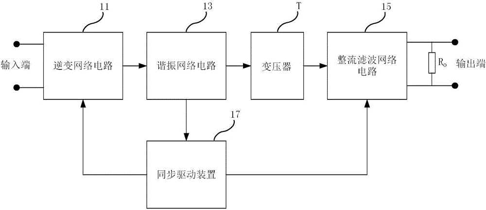
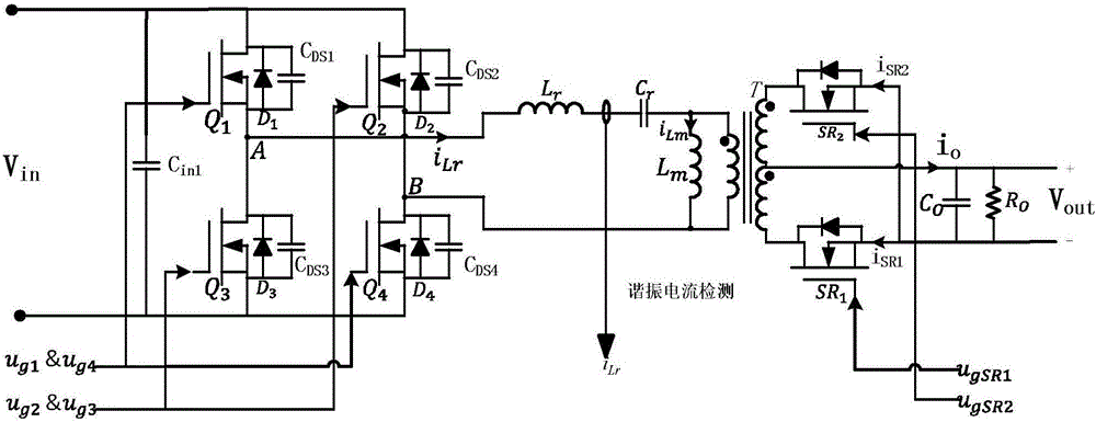
[0049] Please also see figure 2 and image 3 , figure 2 It is a schematic diagram of a circuit module of a full-bridge LLC resonant converter according to an embodiment of the present invention; image 3 It is a circuit structure diagram of a full-bridge LLC resonant converter according to an embodiment of the present invention. The full-bridge LLC resonant converter includes an input terminal (V in ), inverter network circuit (11), resonant network circuit (13), transformer (T), rectifier filter network circuit (15), output load (R O ) and the output (V out ), also includes a synchronous drive (17). specifically:

[0050] The synchronous drive device (17) includes a resonant frequency detection module (171), a synchronous drive module (173), and an isolation drive module (175); wherein, the resonant frequency detection module (171) is based on the resonant network circuit ( 13) The extracted resonant current (i Lr ) to calculate the resonance period (t r ); the syn...

Embodiment 2

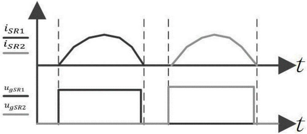
[0060] Please also see Figure 4 and Figure 5 , Figure 4 It is a flowchart of a synchronous rectification digital driving method according to an embodiment of the present invention; Figure 5 It is a schematic diagram of the working principle of a synchronous rectification digital drive device according to an embodiment of the present invention. The method is applied in a full-bridge LLC resonant converter, and the full-bridge LLC resonant converter includes an inverter network circuit (11), a resonant network circuit (13), a transformer (T), and a rectifying and filtering network circuit (15), wherein , the method includes the steps of:

[0061] Step 1, according to the resonant current (i Lr ) to calculate the resonance period (t r );

[0062] Step 2. Compare the switching frequency (f s ) and the resonant period (t r ) converted resonant frequency (f r ) to obtain the comparison result, and determine the synchronous rectification turn-off time (t off );

[0063...


PUM


Abstract

The invention relates to a full-bridge LLC resonant converter and a synchronous rectification driving method thereof. The resonant converter comprises an input end (Vin), an inversion network circuit (11), a resonant network circuit (13), a transformer (T), a rectification filter network circuit (15), an output load (R0) and an output end (Vout) and also comprises a synchronous driving device (17), wherein the synchronous driving device (17) is used for obtaining a resonant period (t<r>) through calculation according to a resonant current (i<Lr>) extracted from the resonant network circuit (13), comparing switching frequency (f<s>) with resonant frequency (f<r>) to obtain a comparison result, determining driving signals (u<g1>&u<g4> and u<g2>&u<g3>) of a primary-side switching tube and driving signals (u<gSR1> and u<gSR1>) of a secondary-side synchronous rectification tube according to the comparison result, and separately sending the driving signals to the inversion network circuit (11) and the rectification filter network circuit (15) so as to control the working of the inversion network circuit (11) and the rectification filter network circuit (15). According to the embodiment of the invention, the synchronous rectification on / off time is determined by comparing the switching frequency with the resonant frequency, the working of the full-bridge LLC resonant converter is flexibly controlled, and the full-bridge LLC resonant converter has the advantages of the simplicity, practicability, high implementability, low cost and the like.

Description

technical field [0001] The invention relates to the technical field of digital circuits, in particular to a full-bridge LLC resonant converter and a synchronous rectification driving method. Background technique [0002] In recent years, the full-bridge LLC resonant converter can realize the turn-on of the primary switch tube ZVS and the turn-off of the secondary rectifier diode ZCS in a wide load range, there is no reverse recovery problem, and the leakage inductance of the transformer can be used to replace the resonant inductance, etc. Advantages have gradually attracted widespread attention from the industry. [0003] However, when outputting low voltage and high current, the rectification loss accounts for a considerable proportion of the total loss due to the increase in the forward conduction voltage drop of the secondary diode of the full-bridge LLC resonant converter, which is not conducive to the improvement of efficiency. Therefore, in order to improve this situa...

Claims


Application Information

Patent Timeline
Patent Type & Authority Applications(China)
IPC IPC(8): H02M3/335
CPCH02M3/33515H02M3/33523H02M3/33592Y02B70/10Y02P80/10
Inventor 宣荣喜滕飞胡辉勇唐子程王斌宋建军舒斌
Owner XIDIAN UNIV
Why Eureka
Try Eureka