Hybrid type quasi-switch voltage-boosting DC-DC converter

A quasi-switching boost, DC-DC technology, which is applied in the field of hybrid high-gain quasi-switching boost DC-DC converter circuits, can solve problems such as being no longer able to meet requirements, achieve convenient control, simple circuit structure, and output The effect of high voltage gain

Active Publication Date: 2016-09-14
DONGGUAN SHILONG FUHUA ELECTRONICS
View PDF3 Cites 9 Cited by
  • Summary
  • Abstract
  • Description
  • Claims
  • Application Information

AI Technical Summary

Problems solved by technology

The Z-source converter and switching boost converter SBI proposed in recent years are both high-gain DC-DC converters, but in some occasions where a low-voltage input is expected to have a higher voltage output, the traditional Z-source converter and SBI converter becomes no longer able to meet the required

Method used


Image

  • Hybrid type quasi-switch voltage-boosting DC-DC converter
  • Hybrid type quasi-switch voltage-boosting DC-DC converter
  • Hybrid type quasi-switch voltage-boosting DC-DC converter

Examples


Embodiment Construction

[0012] The above content has given a detailed description of the technical solution of the present invention, and the specific implementation of the present invention will be further described below with reference to the accompanying drawings.

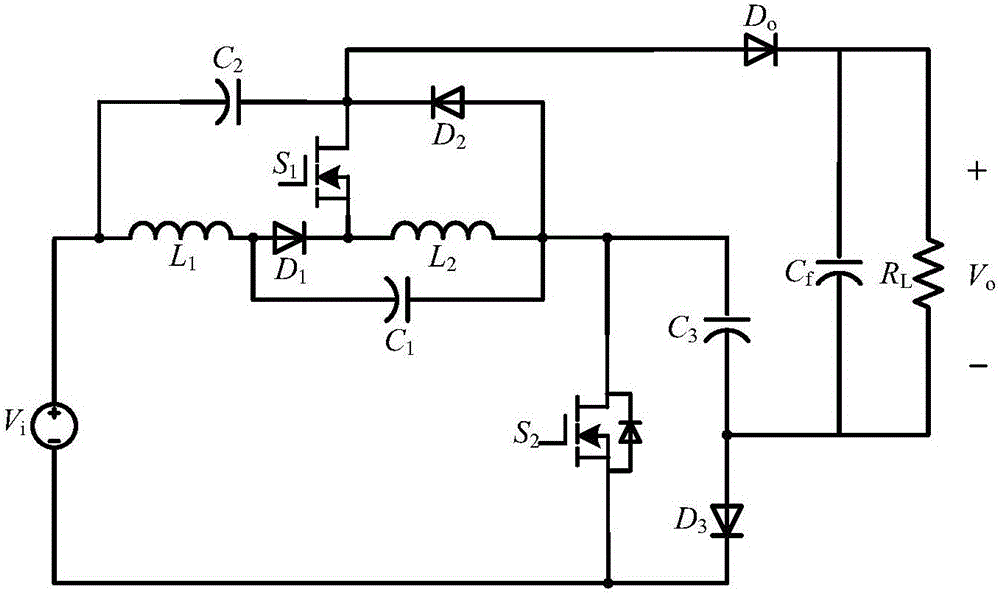
[0013] reference figure 1 , The hybrid quasi-switch boost DC-DC converter circuit of the present invention includes a voltage source, a quasi-Z source unit, a quasi-switch boost unit, a second MOS tube, a switched capacitor unit, an output diode, and an output filter Capacitance and load. The quasi-Z source unit is composed of a first inductor, a first capacitor, a first diode, a second inductor, and a second capacitor; the quasi-switch boost unit is composed of a second inductor, a first diode, and a second capacitor. The capacitor, the first MOS tube and the second diode are formed; the switched capacitor unit is formed by the third capacitor and the third diode.

[0014] The specific connection mode of the circuit of the present inventi...


PUM


Abstract

The invention provides a hybrid type quasi-switch voltage-boosting DC-DC converter. The converter comprises a voltage source, a two-end quasi-Z-source unit which consists of a first inductor, a first diode, a first capacitor, a second inductor and a second capacitor, a quasi-switch voltage-boosting unit which consists of a second capacitor, a second diode, a first MOS transistor, a first diode and a second inductor, a switch capacitor unit which consists of a third capacitor and a third diode, a second MOS transistor, an output diode, an output filtering capacitor and a load. The circuit is simple in structure, combines the single-level voltage-boosting / voltage-bucking characteristics of the quasi-Z-source unit and the quasi-switch voltage-boosting unit as well as the characteristic of the parallel charge and series discharge of the switch capacitor, and expands the output voltage gain.

Description

Technical field [0001] The present invention relates to the technical field of power electronic circuits, in particular to a hybrid high-gain quasi-switching boost DC-DC converter circuit combining a switched capacitor and a quasi-Z source unit. Background technique [0002] In fuel cell power generation and photovoltaic power generation, due to the low DC voltage provided by a single solar cell or a single fuel cell, it cannot meet the electricity demand of existing electrical equipment, nor can it meet the demand for grid connection. It is often necessary to connect multiple batteries Connect in series to achieve the required voltage. On the one hand, this method greatly reduces the reliability of the entire system, on the other hand, it also needs to solve the problem of series voltage equalization. For this reason, a high-gain DC-DC converter capable of converting low voltage to high voltage is required. The Z-source converter and the switching boost converter SBI proposed ...

Claims


Application Information

Patent Timeline
Patent Type & Authority Applications(China)
IPC IPC(8): H02M3/155
CPCH02M3/155H02M3/1552
Inventor 张波朱小全丘东元
Owner DONGGUAN SHILONG FUHUA ELECTRONICS
Why Eureka
Try Eureka