Integrated energy-saving SCR denitration device

A denitration and thermal fluid technology, applied in chemical instruments and methods, dispersed particle separation, lighting and heating equipment, etc., can solve the problems of high reaction temperature, energy waste, high temperature flue gas evacuation, etc., to reduce dust content, reduce Operating cost, effect of reducing operating cost

Active Publication Date: 2016-09-21
北京方信立华科技有限公司
View PDF7 Cites 3 Cited by
  • Summary
  • Abstract
  • Description
  • Claims
  • Application Information

AI Technical Summary

Problems solved by technology

Solve the technical problems of high reaction temperature in the existing SCR denitrification reaction process, and the high-temperature flue gas after the reaction is directly evacuated, resulting in energy waste

Method used


Image

  • Integrated energy-saving SCR denitration device

Examples


Embodiment 1

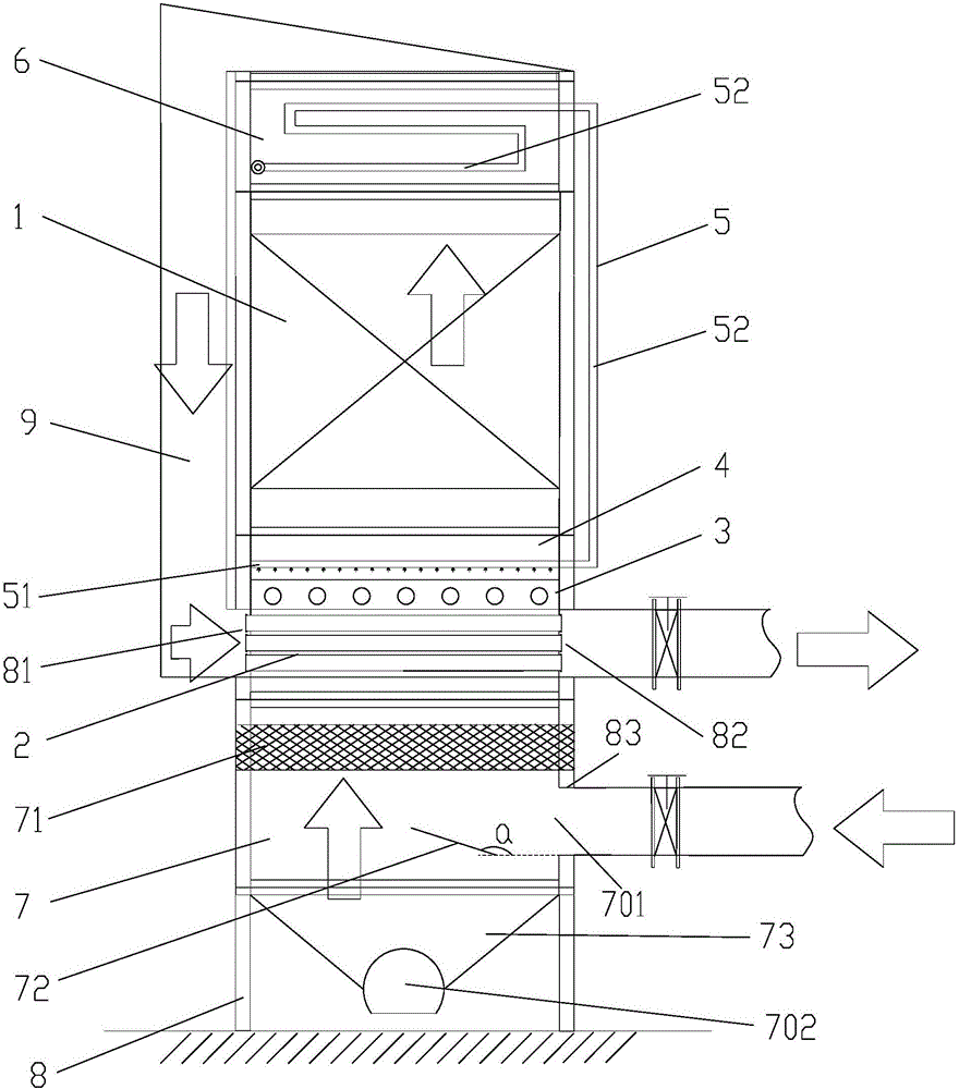
[0028] An integrated energy-saving SCR denitrification device, including an SCR denitrification reaction chamber 1 and a heat exchange chamber 2; port connection; the thermal fluid inlet of the heat exchange chamber 2 is connected to the smoke outlet of the SCR denitration reaction chamber 1, and the thermal fluid outlet is a smoke exhaust port. That is, the pre-reaction flue gas entering the SCR denitrification reaction chamber 1 is used as a cold fluid, and the post-reaction flue gas flowing out of the SCR denitrification reaction chamber 1 is used as a hot fluid, which respectively flows through the heat exchange chamber 2 to utilize the post-reaction flue gas. The residual heat of the flue gas increases the reaction temperature of the pre-reaction flue gas, and the pre-reaction flue gas passing through the heat exchange chamber 2 flows into the SCR denitration reaction chamber to realize the utilization of waste heat and improve resource utilization.

[0029] The heat exch...

Embodiment 2

[0031] The temperature of the pre-reaction flue gas after passing through the heat exchange chamber sometimes does not reach the reaction temperature required by the SCR denitration reaction chamber 1. Therefore, before the pre-reaction flue gas enters the SCR denitration reaction chamber 1, the flue gas temperature needs to be adjusted. .

[0032] Therefore, in the preferred technical solution of Embodiment 2 of the present invention, it also includes a flue gas temperature adjustment chamber 3 and a flue gas temperature control system (not shown in the figure), and a heater (not shown in the figure) is installed in the flue gas temperature adjustment chamber 3 ); the smoke inlet of the flue gas temperature adjustment chamber 3 is connected to the cold fluid outlet of the heat exchange chamber 2, and the smoke outlet is connected to the smoke inlet of the SCR denitration reaction chamber 1.

[0033]The flue gas temperature control system includes a controller and a temperatur...

Embodiment 3

[0036] In the existing SCR denitrification technology, it is necessary to use an appropriate reducing agent (eg, ammonia, urea, etc.) as a reducing agent for catalytic reactions under certain conditions to convert nitrogen oxides into harmless nitrogen and water vapor. Therefore, before the pre-reaction flue gas enters the SCR denitrification reaction chamber 1, it is necessary to add an appropriate amount of reducing agent to the pre-reaction flue gas to promote the catalytic reaction and effectively decompose the harmful substances in the flue gas.

[0037] The preferred technical solution of this embodiment 3 is to further include a gas mixing chamber 4 and a reducing agent supply unit 5; before flowing into the SCR denitration reaction chamber 1, the pre-reaction gas is connected to the gas mixing chamber 4, The flue gas before the reaction after mixing the reducing agent flows into the SCR denitration reaction chamber 1; the gas injection port 51 of the reducing agent supp...


PUM


Abstract

The invention provides an integrated energy-saving SCR denitration device. The integrated energy-saving SCR denitration device comprises an SCR denitration reaction chamber and a heat exchange chamber. Smoke before reaction is fed through a cold fluid inlet of the heat exchange chamber, and a cold fluid outlet is connected with a smoke inlet of the SCR denitration reaction chamber; a hot fluid inlet of the heat exchange chamber is connected with a smoke outlet of the SCR denitration reaction chamber, and a hot fluid outlet is a smoke outlet. Reacted high-temperature smoke serves as hot fluid to heat the smoke before reaction, waste heat of the reacted high-temperature smoke is sufficiently used, the energy use rate is increased, and running cost is reduced. According to the integrated energy-saving SCR denitration device, a dust removing chamber, the heat exchange chamber, a gas mixing chamber, the SCR denitration reaction chamber and a reduction agent evaporation chamber are integrally arranged in a cylinder shell in an optimized mode, design is compact, the pipe conveying flow of smoke is effectively shortened, no pipe is required between every two adjacent chambers, heat losses of smoke in the pipe conveying process are reduced, and meanwhile the occupied area of the denitration device is saved.

Description

technical field [0001] The invention relates to the technical field of SCR denitrification devices, in particular to an integrated energy-saving SCR denitrification device. Background technique [0002] SCR is the most widely used denitrification technology in industry. It can be applied to power plant boilers, industrial boilers, etc. Under ideal conditions, it can make NO x The removal rate of this method is more than 90%. Due to the high efficiency of this method, it is the best one that can be found at present and can be widely used in fixed source NO x Governance technology. The principle of this method is: use an appropriate reducing agent, and under certain conditions, use ammonia as the reducing agent in the catalytic reaction to convert nitrogen oxides into harmless nitrogen and water vapor. [0003] With the large-scale use of SCR denitrification devices in my country, the efficient removal of nitrogen oxides by denitrification equipment has led to a good control...

Claims


Application Information

Patent Timeline
Patent Type & Authority Applications(China)
IPC IPC(8): B01D53/90B01D53/56F23J15/02F23J15/08
Inventor 吴锐孙龙何洪
Owner 北京方信立华科技有限公司
Why Eureka
Try Eureka