
System and method for removing H2S in liquid sulfur

A liquid sulfur removal technology, which is applied in the system field of removing H2S in liquid sulfur, can solve the problems of excessive exhaust gas, affecting sulfur products, and consuming catalysts, etc.

Inactive Publication Date: 2016-09-21
江苏晟宜环保科技有限公司
View PDF8 Cites 4 Cited by
  • Summary
  • Abstract
  • Description
  • Claims
  • Application Information

AI Technical Summary

Problems solved by technology

The first common method is to use a basic catalyst to promote the H 2 For the decomposition of S, commonly used catalysts include ammonia, quinoline, etc.; this method needs to consume catalysts, and the addition of catalysts will affect the quality of sulfur products; the second common method is to spray or stir liquid sulfur to make H 2 S escapes from the liquid flow; ordinary liquid sulfur spray heads are easily blocked, and in order to make liquid sulfur contain H 2 S is less than 10mg / kg, and ammonia injection is required; the third common method is to use air, inert gas or device tail gas to strip liquid sulfur. Since the stripper is built in the liquid flow, the gas bubbles in the stripper to stir the tower Inner liquid sulfur, which is prone to channeling phenomenon, thus reducing the gas stripping effect
For the treatment of degassed waste gas, it is usually sent to the incinerator for incineration, which will cause the exhaust gas SO 2 exceed the standard

Method used


Image

  • System and method for removing H2S in liquid sulfur
  • System and method for removing H2S in liquid sulfur
  • System and method for removing H2S in liquid sulfur

Examples


Embodiment Construction

[0031] In order to make the objectives, technical solutions and advantages of the present invention clearer, the technical solutions in the embodiments of the present invention will be described in more detail below in conjunction with the drawings in the embodiments of the present invention. In the drawings, the same or similar reference numerals denote the same or similar elements or elements having the same or similar functions throughout. The described embodiments are some, but not all, embodiments of the invention. The embodiments described below by referring to the figures are exemplary and are intended to explain the present invention and should not be construed as limiting the present invention. Based on the embodiments of the present invention, all other embodiments obtained by persons of ordinary skill in the art without creative efforts fall within the protection scope of the present invention. Embodiments of the present invention will be described in detail below ...


PUM


Abstract

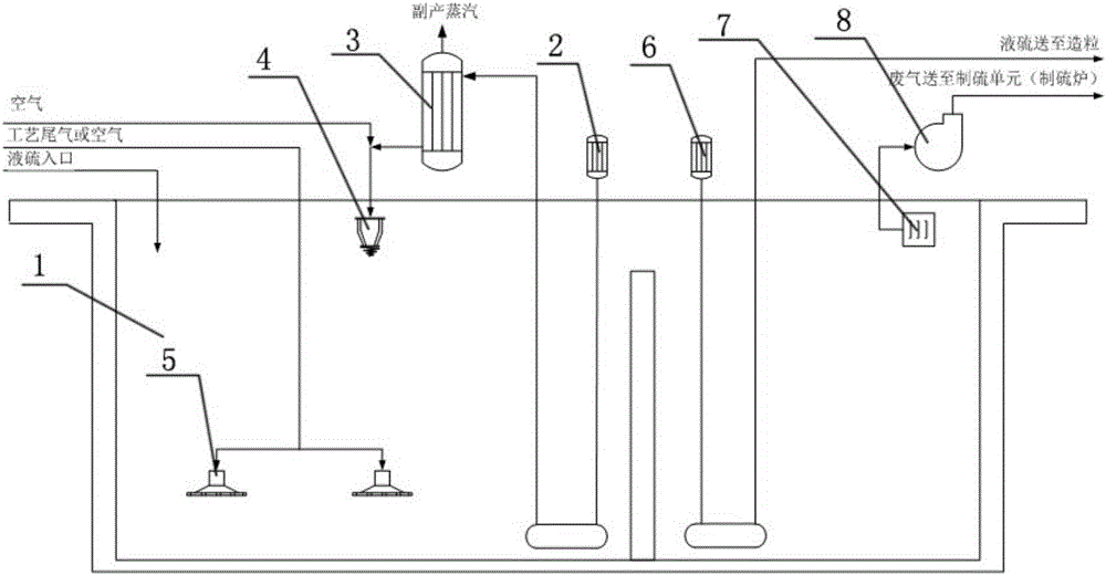
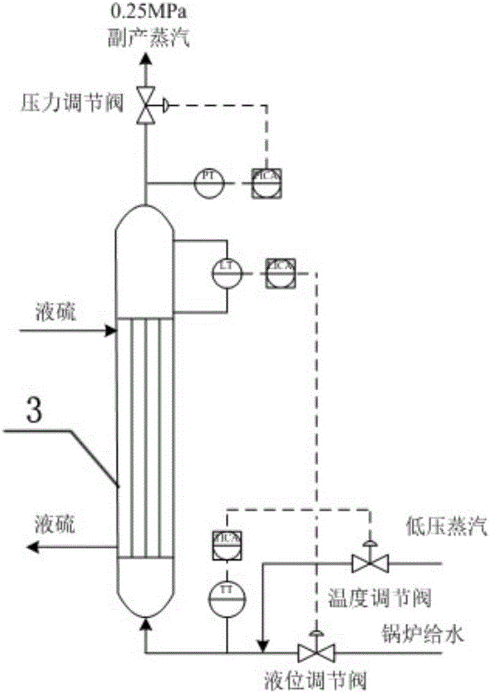
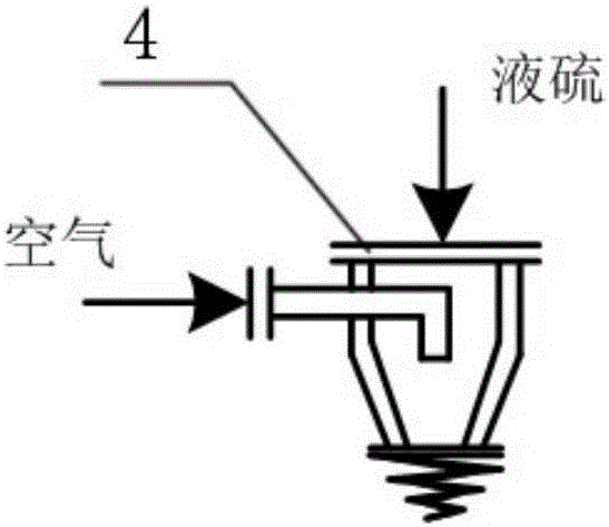
The invention discloses a system and method for removing H2S in liquid sulfur. The system for removing H2S in liquid sulfur comprises a liquid sulfur tank, a liquid sulfur pump, a liquid sulfur cooler, a liquid sulfur spray head, gas stirrers, a product liquid sulfur pump and a waste gas booster fan; liquid sulfur is stored in the liquid sulfur tank; the liquid sulfur pump is connected to the bottom of the liquid sulfur tank to pump liquid sulfur out of the liquid sulfur tank; the liquid sulfur cooler is connected with the liquid sulfur pump, and liquid sulfur pumped by the liquid sulfur pump is cooled in the liquid sulfur cooler; the liquid sulfur spray head is connected with the liquid sulfur cooler, and liquid sulfur cooled by the liquid sulfur cooler is sprayed back to the liquid sulfur tank through the liquid sulfur spray head; the gas stirrers are arranged in the liquid sulfur tank and used for stirring and conducting steam stripping on liquid sulfur in the liquid sulfur tank; the product liquid sulfur pump is connected to the bottom of the liquid sulfur tank, liquid sulfur in which H2S is removed is delivered to a granulation unit through the product liquid sulfur pump; the waste gas booster fan is arranged above the liquid sulfur tank and delivers waste gas to a sulfur production unit.

Description

technical field [0001] The invention relates to the removal of H in liquid sulfur 2 The technical field of S, especially relates to a kind of removal of H in liquid sulfur 2 Systems and methods of S. Background technique [0002] Liquid sulfur produced by sulfur recovery units in oil refining, natural gas, and coal chemical industry has a small amount of H dissolved 2 S, dissolved in liquid sulfur H 2 S will cause various hazards to the environment, safety, health, etc. during storage, molding, and transportation. In order to ensure the safe processing or transportation of liquid sulfur, H dissolved in liquid sulfur must be removed 2 S. [0003] At present, the industrial process adopts the method of removing H from liquid sulfur 2 There are various methods of S, but all have some shortcomings. The first common method is to use a basic catalyst to promote the H 2 For the decomposition of S, commonly used catalysts include ammonia, quinoline, etc.; this method needs t...

Claims


Application Information

Patent Timeline
IPC IPC(8): C01B17/02
CPCC01B17/0232
Inventor 汪刚张盟娟曹妮娜
Owner 江苏晟宜环保科技有限公司
Learn More