Process and system for controlling a process gas stream

a technology of process gas and process flow, applied in separation processes, inorganic chemistry, material testing goods, etc., can solve the problems of affecting altering the ratio from optimal to optimal, and reducing the overall performance or efficiency of the sulfur recovery process. , to achieve the effect of reducing the effect of upset conditions, reducing the duration of the upset effect and the amplitude of the upset

Active Publication Date: 2009-05-12
DREWES VINCENT +1
View PDF22 Cites 1 Cited by
  • Summary
  • Abstract
  • Description
  • Claims
  • Application Information

AI Technical Summary

Benefits of technology

[0017]Further, the present invention is comprised of a control process and a control system for reducing the effects of upset conditions on the recovery of sulfur from the process gas stream, and particularly for reducing the effects of upset conditions related to a variation or sudden change in the composition of the process gas stream. Preferably, the control process and control system of the present invention provide for a reduction in both the duration of the upset effect and the amplitude of the upset effect.
[0018]Further, the control process and control system preferably provide for feed back control, wherein feed back relating to the composition of the process gas stream is utilized to control or vary the amount of the oxygen containing gas in the process gas stream. As a result, the ratio of hydrogen sulfide to oxygen in the process gas stream may be optimized to enhance the sulfur recovery from the process gas stream.
[0038]If desired, the catalytic step may be followed by a further or adjunct processing step for further processing of the process gas stream downstream of the catalytic step. For instance, the adjunct processing step may include a conventional or known tail gas cleanup process or a SUPERCLAUS™ step conducted downstream of the catalytic step, and particularly downstream of the end of the catalytic step. Preferably, the adjunct processing step is comprised of a SUPERCLAUS™ step including a catalytic reaction utilizing a selective oxidation catalyst capable of enhancing the efficiency of the oxidization of the hydrogen sulfide in the process gas stream.

Problems solved by technology

In addition, amounts of hydrogen sulfide and sulfur dioxide typically remain unreacted.
A sudden change in the composition or flow rate of the process gas, causing a sudden change in the oxygen demands, is referred to as an “upset condition.” During upset conditions, a resulting alteration in the ratio from the optimal tends to adversely impact upon the sulfur recovery rate.
It has been found that even small temporary deviations from the optimal may cause a considerable decrease in the overall performance or efficiency of the sulfur recovery processes.
However, the disadvantage of basing control on the composition of the tail gas is that there is a relatively significant time delay between the time that the hydrogen sulfide containing process gas enters the thermal step and the time that the tail gas exits the catalytic step.
As a result, during “upset conditions” where the composition, and thus the air demands, of the hydrogen sulfide containing process gas entering the thermal step changes suddenly, there is a delay of at least about two to three minutes before the control system based upon the composition of the tail gas recognizes the occurrence of the upset conditions.
The end result of utilizing the composition of the tail gas as the basis of controlling the amount of air which is added to the hydrogen sulfide containing process gas before the thermal step is that the occurrence of upset conditions continue to reduce the overall efficiency of the Claus process and SUPERCLAUS™ step.
However, although sampling the process gas nearer the thermal step increases the speed at which the feed back is provided to the control system, it has been found that such samples provide for a relatively less accurate measure of process conditions as compared with sampling of the tail gas.
However, for the reasons discussed above, none of these control systems have been found to be fully satisfactory.

Method used


Image

  • Process and system for controlling a process gas stream
  • Process and system for controlling a process gas stream
  • Process and system for controlling a process gas stream

Examples


Embodiment Construction

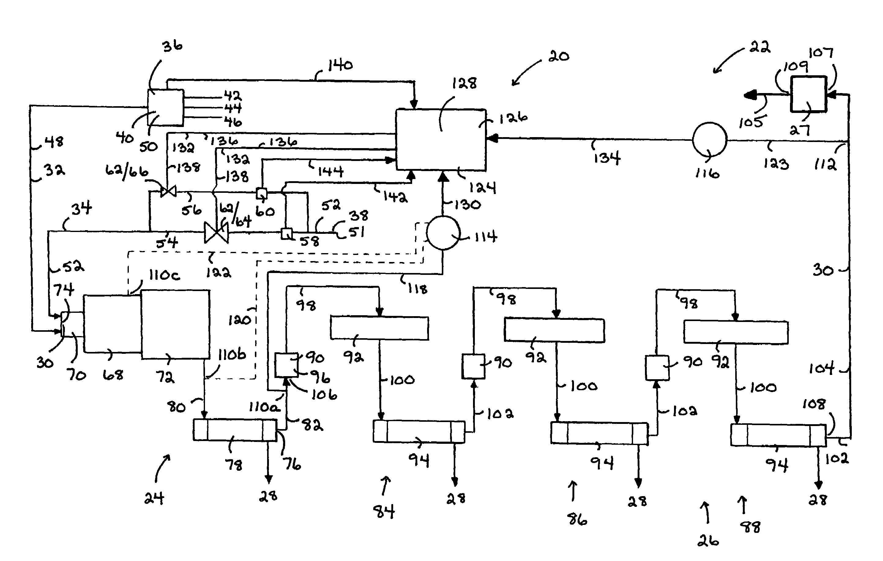
[0082]Referring to FIG. 1, the present invention is directed at a control process and a control system (20) for use in conjunction or association with a sulfur recovery process or sulfur recovery system or unit (22) respectively. Preferably, the sulfur recovery process is comprised of a thermal step and a catalytic step. The sulfur recovery system (22) is preferably comprised of a thermal reaction apparatus (24) for performing the thermal step and a catalytic reaction apparatus (26) for performing the catalytic step. More particularly, in the preferred embodiment of the control process of the present invention, the control process is used in association or conjunction with a Claus sulfur recovery process which comprises the thermal and catalytic steps. Further, in the preferred embodiment of the control system (20) of the present invention, the control system (20) is used in association or conjunction with a Claus sulfur recovery system or unit which comprises the thermal and cataly...


PUM

PropertyMeasurementUnit
response timeaaaaaaaaaa
compositionaaaaaaaaaa
temperatureaaaaaaaaaa

Abstract

In a process and system for recovering sulfur from a process gas stream initially comprising a hydrogen sulfide containing gas and an oxygen containing gas, a control process and system respectively are provided. The sulfur recovery process includes a thermal step having a beginning followed by a catalytic step having an end. The control process includes first analyzing a composition of the process gas stream at a first location between the beginning of the thermal step and the end of the catalytic step, first controlling the oxygen containing gas having regard to that first composition, second analyzing the composition of the process gas stream at a second location downstream of the end of the catalytic step, and second controlling the oxygen containing gas having regard to that second composition. The sulfur recovery system and control system therefor are provided for performing the steps of the sulfur recovery process and control process respectively.

Description

FIELD OF INVENTION[0001]The present invention is for use in a process and a system for recovering sulfur from a process gas stream initially comprising a hydrogen sulfide containing gas and an oxygen containing gas. Specifically, the present invention relates to a control process and a control system for controlling the amount of the oxygen containing gas in the process gas stream.BACKGROUND OF INVENTION[0002]Process gases, such as those resulting from gas plants and refineries or as a by-product of other industrial processes, may contain an amount of hydrogen sulfide. The recovery of sulfur from these process gases provides a valuable sulfur product. In addition, the sulfur is also preferably removed from the process gases prior to the disposal of the gas, such as through flaring or venting of the process gas to the atmosphere, in order to reduce any atmospheric pollution which may result therefrom.[0003]Accordingly, various sulfur extraction and recovery systems have been develope...

Claims


Application Information

Patent Timeline
Patent Type & Authority Patents(United States)
IPC IPC(8): G01N21/00C01B17/00C01B17/02G01N35/08
CPCB01D53/8612C01B17/0452C01B17/0413Y10T436/12
Inventor D'HA NE, PAUL E.SCHERMANN, PETER S.
Owner DREWES VINCENT
Why Eureka
Try Eureka