Eureka AIR delivers breakthrough ideas for toughest innovation challenges, trusted by R&D personnel around the world.

Obstacle avoidance type snow sweeping device

A technology for obstacle avoidance and driving devices, which is applied in snow surface cleaning, cleaning methods, construction, etc., can solve problems such as waste of resources, snowmelt pollution, corrosion of road surfaces, etc., and achieve a high degree of automation, a wide range of applications, and increase the operating width. Effect

Inactive Publication Date: 2016-09-21
SHIHEZI UNIVERSITY
View PDF6 Cites 0 Cited by
  • Summary
  • Abstract
  • Description
  • Claims
  • Application Information

AI Technical Summary

Problems solved by technology

[0002] There is a lot of snow in northern my country in winter, but due to the cold weather, the snow cannot melt in time, and a layer of hard ice will be formed under the long-term rolling of the wheels, causing slippery roads, prone to traffic accidents, and causing many unnecessary personal and property losses For traffic safety, the only way to remove the ice and snow is to remove the snow. At present, the following methods are used: first, manual snow removal is slow, time-consuming and labor-intensive, and requires a lot of investment; Cause salt pollution and corrode the road surface; thirdly, use mechanical snow pushing, this method is fast and effective, but it can only be used on straight and wide urban roads, and the snow near the turning ramps or green belt plants cannot be cleaned and can only be piled At the corner of the ramp or around the plants, it occupies the road area, affects the passage of people and vehicles, and also causes snowmelt pollution when the snow melts
[0003] Most of the existing snowplows are fixed-width type, and the snowplowing path is fixed during work. It has poor adaptability to special occasions such as pedestrian crosswalks with rows of green plants, and the snowplowing effect is not ideal; snowplowing devices with variable path function mostly use hydraulic cylinders. The control realizes the left and right movement of the snow-plowing roller, but the expansion and contraction of the oil cylinder is controlled manually. When the driver visually observes the change of the road surface and needs to swing the roller, he presses the switch, and the action of the oil cylinder drives the roller brush to swing.
Due to the artificial control, the control accuracy is not high, and it is easy to cause damage to the roller brush due to untimely control

Method used


Image

  • Obstacle avoidance type snow sweeping device
  • Obstacle avoidance type snow sweeping device
  • Obstacle avoidance type snow sweeping device

Examples


Embodiment 1

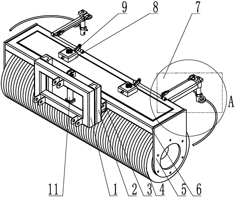
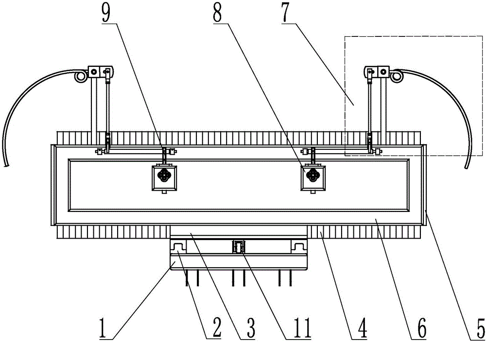
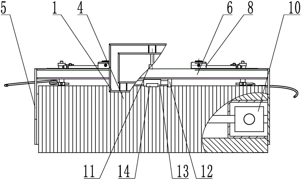
[0029] Embodiment 1: refer to Figure 1~5 , is a structural schematic diagram of Embodiment 1 of the present invention, an obstacle-avoiding snow removal device, including a fixed frame 1, a mobile frame 6, an obstacle sensing and signal transmission mechanism 7, a hydraulic valve 8, and a driving device for a snow removal roller assembly 10 and the snow-plowing roller assembly 4, which is characterized in that: the fixed frame 1 and the mobile frame 6 are provided with a mobile connection mechanism, the lower part of the mobile frame 6 is provided with a snow-plowing roller assembly 4, and the front part of the mobile frame An obstacle induction and signal transmission mechanism 7 is provided on the side; the mobile connection mechanism includes a chute mechanism and a hydraulic drive mechanism, and the chute mechanism includes a fixed frame chute 2 on a fixed frame 1 and a fixed frame on the mobile machine. The mobile frame chute 3 on the frame 6; the hydraulic drive mechani...

Embodiment 2

[0033] Embodiment 2: refer to Figure 6-8 It is a structural schematic diagram of Embodiment 2 of the present invention. Compared with Embodiment 1, this embodiment differs in that: the chute mechanism between the fixed frame 1 and the mobile frame 6 is a parallel four-bar mechanism 31 .

[0034] In actual use: the hydraulic oil then enters the traverse cylinder 13, that is, enters a cavity of the double-acting double-piston rod hydraulic cylinder or the single-acting plunger cylinder, and the piston rod on one side shrinks, so that the parallel four-bar mechanism 31 performs reverse deflection, Thereby drive the mobile frame 6 pinned with it to move laterally, to reach the purpose of avoiding obstacles.

Embodiment 3

[0035] Embodiment 3: refer to Figure 9 It is a structural schematic diagram of Embodiment 3 of the present invention. Compared with Embodiment 1 or Embodiment 2, this embodiment differs in that: the driving device 10 of the snow-plowing roller assembly is a hydraulic motor, and the snow-plowing roller assembly The driving device 10 can be arranged in the snow-plowing roller assembly 4 or on the frame 6 , and is connected with the snow-plowing roller assembly 4 through a transmission chain 15 .

[0036] In actual use: different installation positions of the driving device 10 of the snow-plowing roller assembly are selected according to different working conditions, so as to complete the work more efficiently.


PUM


Abstract

The invention provides an obstacle avoidance type snow sweeping device. The obstacle avoidance type snow sweeping device comprises a fixed rack (1), a movable rack (6), an obstacle induction and signal transmission mechanism (7), hydraulic valves (8), a snow sweeping roller assembly driving device (10) and a snow sweeping roller assembly (4). The obstacle avoidance type snow sweeping device is characterized in that a movable connecting mechanism is arranged between the fixed rack (1) and the movable rack (6), the snow sweeping roller assembly (4) is arranged on the lower portion of the movable rack (6), and the obstacle induction and signal transmission mechanism (7) is arranged on the lateral of the front portion of the movable rack. Compared with the prior art, the obstacle avoidance type snow sweeping device has the characteristics that the structure is simple; the automation degree is high; the operation width can be increased; the operation path is automatically changed; obstacle avoidance operation is achieved; the operating occasion can be broadened; the application scope is wide; the operating efficiency is high; snow removing is thorough and clean; and the operating speed is high.

Description

technical field [0001] The invention relates to the field of highway driving safety traffic, in particular to an obstacle-avoiding snow removal device. technical background [0002] There is a lot of snow in northern my country in winter, but due to the cold weather, the snow cannot melt in time, and a layer of hard ice will be formed under the long-term rolling of the wheels, causing slippery roads, prone to traffic accidents, and causing many unnecessary personal and property losses For traffic safety, the only way to remove the ice and snow is to remove the snow. At present, the following methods are used: first, manual snow removal is slow, time-consuming and labor-intensive, and requires a lot of investment; Cause salt pollution and corrode the road surface; thirdly, use mechanical snow pushing, this method is fast and effective, but it can only be used on straight and wide urban roads, and the snow near the turning ramps or green belt plants cannot be cleaned and can onl...

Claims


Application Information

Patent Timeline
Patent Type & Authority Applications(China)
IPC IPC(8): E01H5/09
CPCE01H5/092
Inventor 毕新胜袁昌富王斌蔡贺王志欢张新超
Owner SHIHEZI UNIVERSITY
Why Eureka
Eureka Blog
Learn More