Conformal antenna array seeker modeling simulation method

A technology of conformal antenna and simulation method, applied in design optimization/simulation, special data processing applications, instruments, etc., can solve the problem of less beam synthesis

Inactive Publication Date: 2016-09-21
SHANGHAI INST OF ELECTROMECHANICAL ENG
View PDF2 Cites 14 Cited by
  • Summary
  • Abstract
  • Description
  • Claims
  • Application Information

AI Technical Summary

Problems solved by technology

At present, there are relatively few studies on the beam synthesis of antenna arrays composed of dire

Method used


Image

  • Conformal antenna array seeker modeling simulation method
  • Conformal antenna array seeker modeling simulation method
  • Conformal antenna array seeker modeling simulation method

Examples


Embodiment Construction

[0036] The present invention will be further elaborated below by describing a preferred specific embodiment in detail in conjunction with the accompanying drawings.

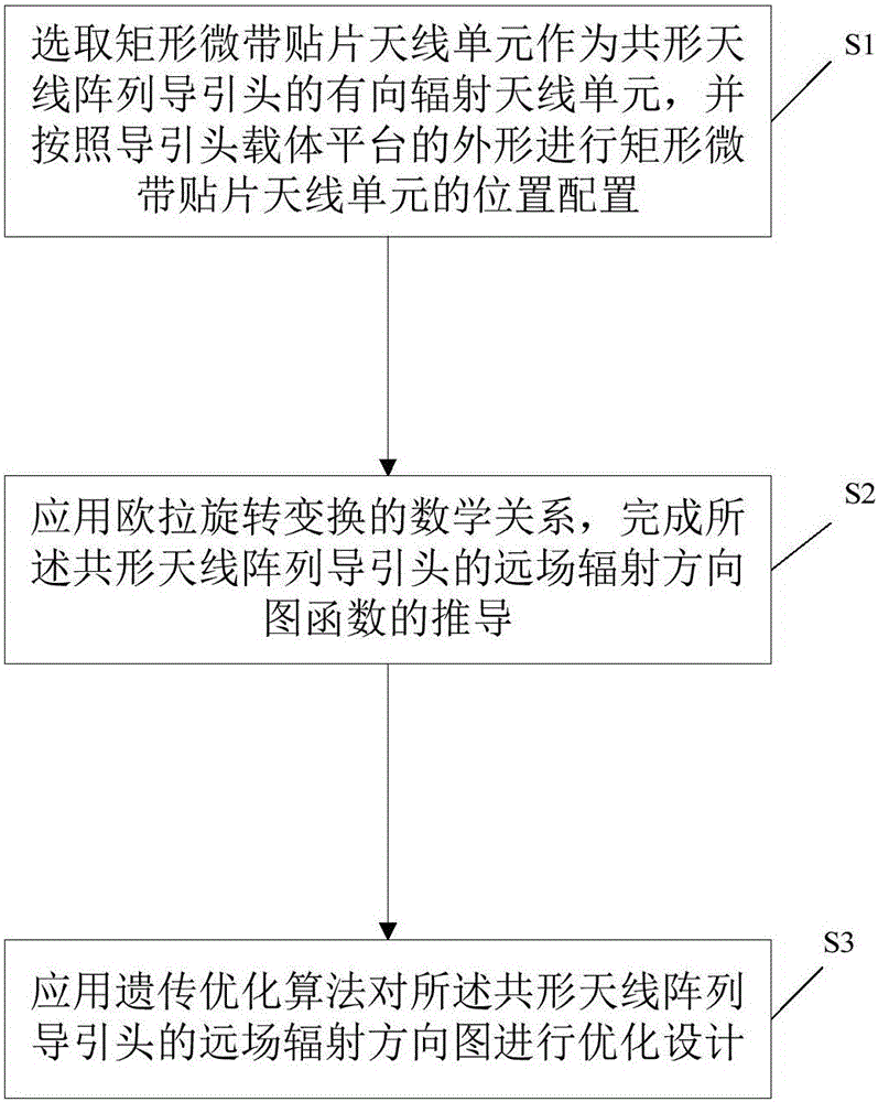
[0037] Such as figure 1 As shown, a modeling simulation method guided by a conformal antenna array, including:

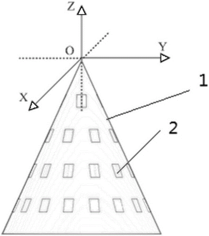
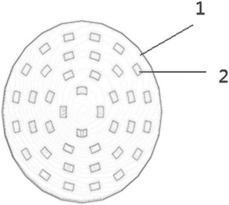
[0038] S1, select the rectangular microstrip patch antenna unit 2 as the directional radiation antenna unit of the conformal antenna array seeker 1, and configure the position of the rectangular microstrip patch antenna unit 2 according to the shape of the seeker carrier platform, several A rectangular microstrip patch antenna unit forms an antenna array;

[0039] S2, applying the mathematical relationship of the Euler rotation transformation to complete the derivation of the far-field radiation pattern function of the conformal antenna array seeker 1;

[0040] S3, applying a genetic optimization algorithm to optimize the design of the far-field radiation pattern of the conformal antenna array seeker...


PUM


Abstract

The present invention discloses a conformal antenna array seeker modeling simulation method. The method comprises: S1. selecting rectangular microstrip patch antenna elements as directed radiation antenna elements of a conformal antenna array seeker, and performing location configuration on the rectangular microstrip patch antenna elements according to a shape of a seeker carrier platform, wherein a plurality of rectangular microstrip patch antenna elements form an antenna array; S2. applying a mathematical relationship of Euler rotation transformation to complete derivation of a far-field radiation pattern function of the conformal antenna array seeker; and S3. applying a genetic optimization algorithm to optimally design a far-field radiation pattern of the conformal antenna array seeker. By use of the method disclosed by the present invention, a radar diffusion cross section of the seeker can be reduced, an excellent electromagnetism stealth property is achieved, and the highest sidelobe value of the far-field radiation pattern is significantly improved.

Description

technical field [0001] The invention relates to the related technical field of the digital array radar seeker, in particular to a method for simulating and optimizing the antenna unit layout and radiation pattern of the conformal antenna array seeker. Background technique [0002] At present, the guidance antenna of the traditional radar seeker is usually placed inside the fairing (namely the nose cone) of the missile head, and it is generally a planar antenna array. Although the calculation model of the planar antenna array is simple and the technology is becoming more and more mature, there are some inherent shortcomings. For example, the scanning range of the antenna beam is limited to 120°, and the beam width will widen with the increase of the scanning angle. The corresponding antenna gain and Scanning accuracy decreases as the scan angle increases. In addition, the mutual coupling effect between units satisfies a functional relationship with the scan angle, and the st...

Claims


Application Information

Patent Timeline
IPC IPC(8): G06F17/50
CPCG06F30/20
Inventor 康传华栗高峰郑晟于冰王晓科朱莹刘岚董帅君
Owner SHANGHAI INST OF ELECTROMECHANICAL ENG
Why Eureka
Try Eureka