Glasses-free three-dimensional display device based on active light-emitting display technology

A technology of active light-emitting and display technology, applied in image communication, electrical components, stereo systems, etc., can solve the problems of difficult to achieve uniform lighting, difficult to integrate, difficult to manufacture, etc., to achieve easy uniform lighting, huge commercial value, lighting The effect of the scheme is simple

Active Publication Date: 2017-12-22
SVG TECH GRP CO LTD +1
View PDF8 Cites 5 Cited by
  • Summary
  • Abstract
  • Description
  • Claims
  • Application Information

AI Technical Summary

Problems solved by technology

In this technology, although the amplitude modulation method of LED side lighting has the advantage of small size, it is difficult to process, high in cost, demanding in installation accuracy, and difficult to achieve uniform lighting.
[0010] Chinese patent 2015107780865 discloses a directional color filter and a naked-eye 3D display device. It is proposed that laser projection can be used to achieve high-brightness and uniform lighting of the directional light field. However, the lighting system is large and difficult to integrate and difficult to realize. ultra thin display
However, the design accuracy of the directional light guide plate is demanding, the production is difficult, the processing cost is high, and it is difficult to achieve industrialized mass production. At the same time, this method is not suitable for large-format 3D display methods.
In the field of large-format and high-brightness 3D display, people have designed a 3D display solution based on laser projection and scanning display technology, but this method is difficult to achieve the integration and ultra-thinness of the display screen
At the same time, laser display technology has not yet matured, and the cost is relatively high

Method used


Image

  • Glasses-free three-dimensional display device based on active light-emitting display technology
  • Glasses-free three-dimensional display device based on active light-emitting display technology
  • Glasses-free three-dimensional display device based on active light-emitting display technology

Examples


Embodiment Construction

[0055] Preferred embodiments of the present invention will be described in detail below in conjunction with the accompanying drawings.

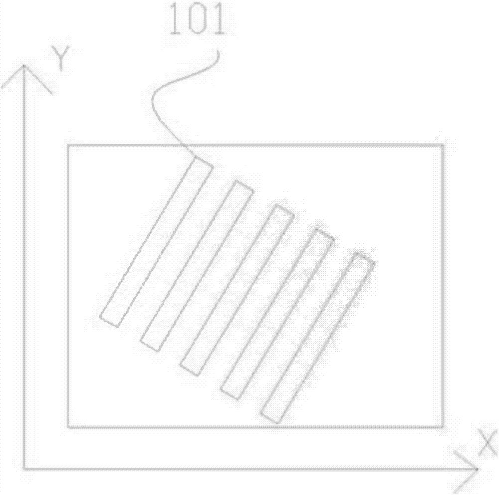
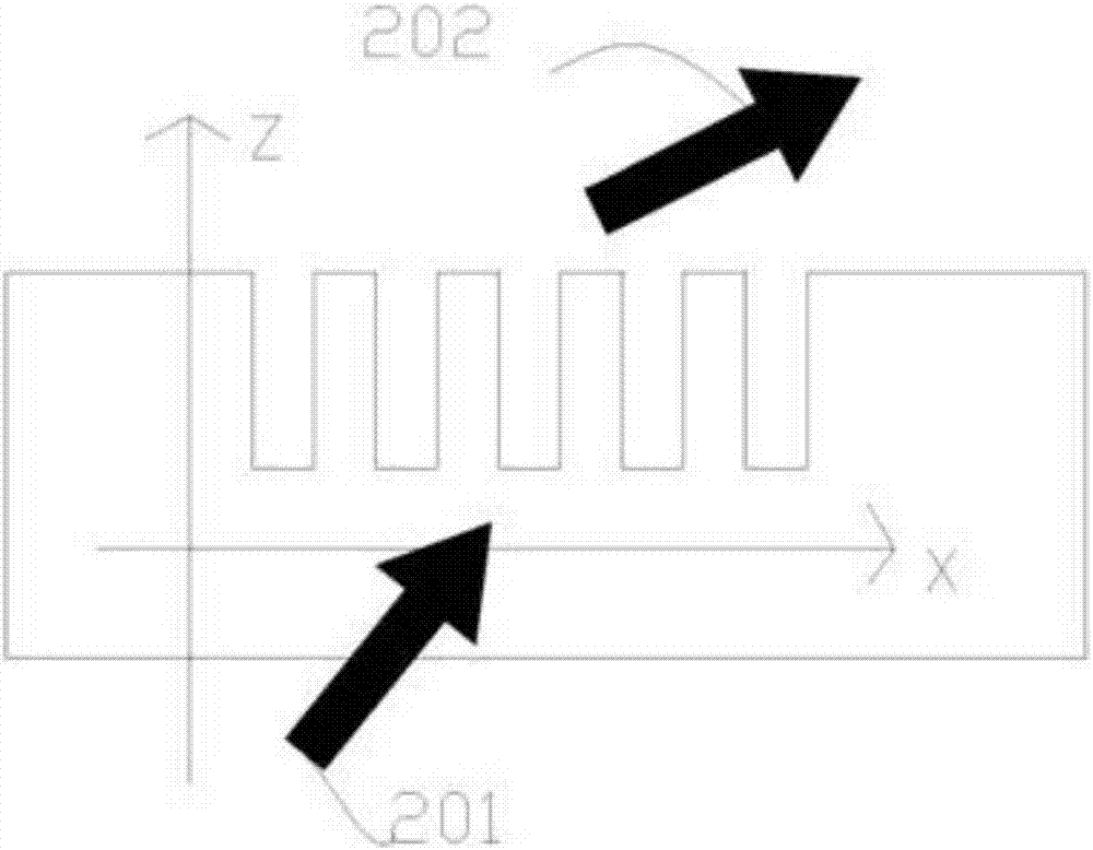
[0056] see Figure 1-2 , according to the grating equation, the period and orientation angle of the diffraction grating pixel 101 satisfy the following relationship:

[0057] (1) tanφ 1 = sinφ / (cosφ-nsinθ(Λ / λ));

[0058] (2) sin 2 (θ 1 )=(λ / Λ) 2 +(nsinθ) 2 -2nsinθcosφ(λ / Λ).

[0059] Among them, light is incident on the XY plane at a certain angle, θ1 and φ1 successively represent the diffraction angle of the diffracted light 202 (the angle between the diffracted light and the positive direction of the z-axis) and the azimuth angle of the diffracted light 202 (the angle between the diffracted light and the positive direction of the x-axis) angle), θ and λ successively represent the incident angle of the light source 201 (the angle between the incident light and the positive direction of the z-axis) and wavelength, and ∧ and φ represent ...


PUM


Abstract

The invention discloses a naked eye three-dimensional display device based on an active emitting type display technology. The device comprises an active emitting display unit, wherein the display unit comprises an emitting array adjustable in light strength, and according to multi-visual-angle superposed images, the emitting array modulates a light field amplitude through a circuit control system; and a directive phase plate, wherein the pixels of the directive phase plate contains nano-grating pixel structures which are respectively corresponding to sub-pixels of the visual-angle images, the nano-grating pixel structures contains nano-grating combinations which are designed according to a holographic principle, the nano-grating pixel structures carry out wavefront conversion on incident visual-angle images after light emitted by the active emitting display unit is irradiated to the directive phase plate, and a convergence viewpoint of parallel illumination light is formed in the space in front of or at the side surface of the active emitting display unit. Compared with the prior art, the demands of personal consumption electronic markets and industrial and outdoor display markets are simultaneously met, and naked eye three-dimensional display which is ultra-thin, convenient, large in area, high in brightness and low in cost is realized.

Description

technical field [0001] The invention relates to a display device, in particular to a naked-eye three-dimensional display device based on active light-emitting display technology. Background technique [0002] Active light-emitting display devices have self-illumination and do not require a backlight source. They are considered to be the next-generation flat-panel display emerging application technology, including LED display technology and OLED display technology. [0003] The LED display screen is composed of LED dot matrix, and the image is displayed by turning on and off the red, blue and green LED lights. A traditional LED display is usually composed of a display module, a control system and a power supply system. The display module is composed of a dot matrix of LED lights, which is responsible for luminous display; the control system can display text, pictures, videos and other content on the screen by controlling the corresponding areas to turn on and off. The reaso...

Claims


Application Information

Patent Timeline
Patent Type & Authority Patents(China)
IPC IPC(8): H04N13/04
Inventor 乔文陈林森朱鸣万文强黄文彬浦东林朱鹏飞方宗豹
Owner SVG TECH GRP CO LTD
Why Eureka
Try Eureka