
Integral clip-type anchor structure device and assembly method thereof

An integrated, clip-type technology, applied in the direction of basic structure engineering, building construction, bridge parts, etc., can solve the problem of small bonding area between FRP tendons or strands and anchoring medium, low sliding friction and mechanical bite force, Problems such as large geometric dimensions, to achieve high anchorage efficiency, avoid early fracture, and reduce stress peaks

Active Publication Date: 2018-04-06
CHINA JINGYE ENG TECH CO LTD +1
View PDF8 Cites 0 Cited by
  • Summary
  • Abstract
  • Description
  • Claims
  • Application Information

AI Technical Summary

Problems solved by technology

However, engineering practice has shown that the bonded anchorage used for FRP tendons or strands has some inherent technical defects, such as large geometric size, relatively bulky, low rigidity, and the bonding area between FRP tendons or strands and the anchoring medium is small , the sliding friction and mechanical bite force are low, and it is easy to produce prestress loss and creep, etc.

Method used


Image

  • Integral clip-type anchor structure device and assembly method thereof
  • Integral clip-type anchor structure device and assembly method thereof
  • Integral clip-type anchor structure device and assembly method thereof

Examples


Embodiment 1

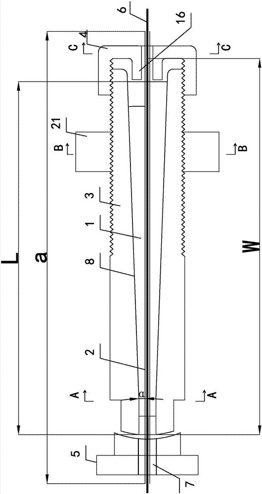
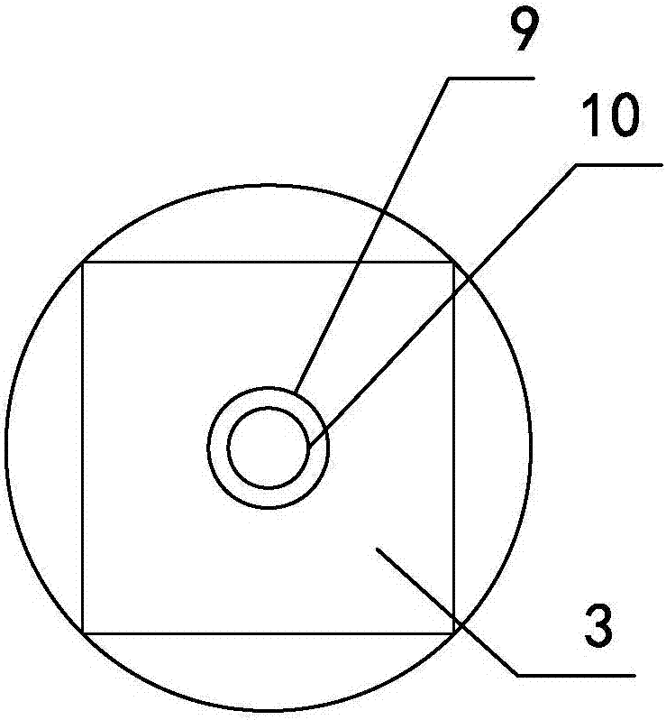
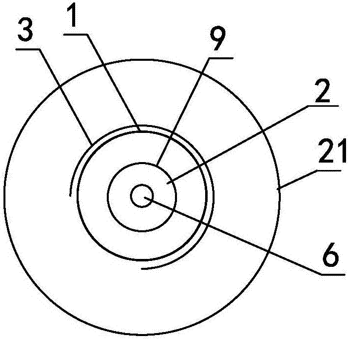
[0078] Such as Figure 1 to Figure 7 As shown, the wire 6 of this embodiment is a CFRP stranded wire with a diameter of 12mm composed of 7 carbon fiber bundles. The anchorage structural device includes an integrated clip structure 1, a soft metal sheath 2, and an external Anchor ring 3 with thread and lock nut 21, rear jacking part 4 and anchor plate 5, wherein anchor plate 5 is a spherical anchor plate, and rear jacking part 4 is a bolt.

[0079] The middle part of the anchor ring 3 is provided with an inner tapered hole 8 extending along its center line. The inner tapered hole 8 is provided with an integrated clip structure 1 matching its shape. The axial length L of the integrated clip structure 1 is less than or equal to the anchor ring. The axial length W of the ring 3 . The one-piece clip structure 1 is made of stainless steel and integrally spliced ​​by a short cylinder 13 and a slender round platform, and the outer envelope line of its longitudinal section is an obliq...

Embodiment 2

[0094] Such as Figure 9 As shown, the difference between this embodiment and the first embodiment is that the wire 6 is an embossed BFRP tendon of basalt fiber reinforced composite material, the anchor plate 5 is a plane anchor plate, and the left end of the anchor ring 3 is in plane contact with the plane anchor plate. The included angle θ is 3°, and the included angle α is 2.9°. The axial length L of the one-piece clip structure 1 is greater than the axial length W of the anchor ring 3 , and when in use, the front end of the one-piece clip structure 1 can extend out of the anchor ring 3 to the left.

[0095] The cross-section of the soft metal sheath 2 is two semicircular rings buckled together, which are made of copper foil with a thickness of 0.8mm. The inner walls of the two semicircular soft metal sheaths 2 are sealed with epoxy resin glue. Paste 120-mesh quartz sand to form a protective layer that increases friction. The BFRP tendon in the anchoring area wraps the so...

Embodiment 3

[0098] Such as Figure 10 , Figure 11 As shown, this embodiment is an AFRP bar full-length bonded rock bolt applied to rock slope anchoring engineering, that is, a tension-type full-length bonded rock bolt. The anchoring structure is a rocky slope. The difference between this embodiment and the second embodiment is that the device wire 6 of the present invention is an embossed AFRP bar of a single aramid fiber reinforced composite material with a length of 21 m and a diameter of 20 mm, and the rear jacking part 4 is an anti-corrosion nut cap. The axial length L of the one-piece clip structure 1 is less than or equal to the axial length W of the anchor ring 3 , and the one-piece clip structure 1 is placed inside the anchor ring 3 during use.

[0099] The principle of the assembly method in Embodiment 1 is the same, the construction steps of the AFRP tendon tensile type full-length bonded rock bolt assembly method in this embodiment are as follows:

[0100] a. Drill a rock a...


PUM


Abstract

The invention relates to an integrated clamping piece type anchor structure device and an assembling method thereof. The anchor structure device comprises an anchor ring with a lock nut and an external thread. The middle of the anchor ring is provided with an inner cone hole extending along a center line of the anchor ring, an integrated clamping piece structure with the appearance matched with the appearance of the inner cone hole is arranged in the inner cone hole, the middle of the integrated clamping piece structure is provided with a cylindrical center hole extending along a center line of the integrated clamping piece structure, a hollow cylindrical soft metal sheath is arranged in the center hole, a wire rod penetrates into the soft metal sheath, one end of the anchor ring is matched with an anchor plate with the middle provided with a cylindrical through hole, and the other end of the anchor ring is in screwed connection with a rear pushing component. The rear pushing component and the anchor plate are located at the thick end and the thin end of the integrated clamping piece structure respectively, and center lines of the inner cone hole, the center hole, the through hole and the wire rod coincide. The objective is to provide the integrated clamping piece type anchor structure device which is safe, reliable, convenient to assemble, economical and practical and is used for high performance fiber reinforced composite material ribs or stranded wires and the assembling method thereof.

Description

technical field [0001] The present invention relates to a special anchorage structure device for civil engineering and its assembly process, in particular to a special end anchoring system for high-performance fiber reinforced composite (FRP) tendons or stranded wires, and the anchorage structure device assembly method. Background technique [0002] High-performance fiber reinforced composites (FRP) have excellent properties such as high strength, corrosion resistance, low relaxation, fatigue resistance, non-magnetic, low density, low thermal expansion coefficient, and good shock absorption performance. Therefore, carbon fiber reinforced composites (CFRP) , basalt fiber reinforced composites (BFRP) and aramid fiber reinforced composites (AFRP) are used in geotechnical anchoring engineering, suspension and cable-stayed bridge engineering, space cable net structure engineering or concrete structure engineering on coasts and islands, and can be used The new material replacemen...

Claims


Application Information

Patent Timeline
Patent Type & Authority Patents(China)
IPC IPC(8): E04G21/12E02D5/74E01D19/16
CPCE01D19/16E02D5/74E04G21/12
Inventor 刘钟岳清瑞郭钢张义
Owner CHINA JINGYE ENG TECH CO LTD
Learn More