Switching converter for constant turn-on time control and automatic calibration method thereof

A constant on-time, switching converter technology, applied in electronic switches, control/regulation systems, output power conversion devices, etc., can solve problems such as different on-times and affecting product consistency

Active Publication Date: 2016-09-28
CHENGDU MONOLITHIC POWER SYST
View PDF6 Cites 10 Cited by
  • Summary
  • Abstract
  • Description
  • Claims
  • Application Information

AI Technical Summary

Problems solved by technology

[0004] In the mass-manufacturing process, process deviations (such as deviations in resistance values, capacitance values, or comparator delays) will affect the above-mentioned on-time control circuit, causing converters with the same design to operate under the same input and output voltage conditions. The resulting turn-on time is different, which affects the consistency of the product

Method used


Image

  • Switching converter for constant turn-on time control and automatic calibration method thereof
  • Switching converter for constant turn-on time control and automatic calibration method thereof
  • Switching converter for constant turn-on time control and automatic calibration method thereof

Examples


Embodiment Construction

[0019] Specific embodiments of the present invention will be described in detail below, and it should be noted that the embodiments described here are only for illustration, not for limiting the present invention. In the following description, numerous specific details are set forth in order to provide a thorough understanding of the present invention. It will be apparent, however, to one of ordinary skill in the art that these specific details need not be employed to practice the present invention. In other instances, well-known circuits, materials or methods have not been described in detail in order to avoid obscuring the present invention.

[0020] Throughout this specification, reference to "one embodiment," "an embodiment," "an example," or "example" means that a particular feature, structure, or characteristic described in connection with the embodiment or example is included in the present invention. In at least one embodiment. Thus, appearances of the phrases "in on...


PUM


Abstract

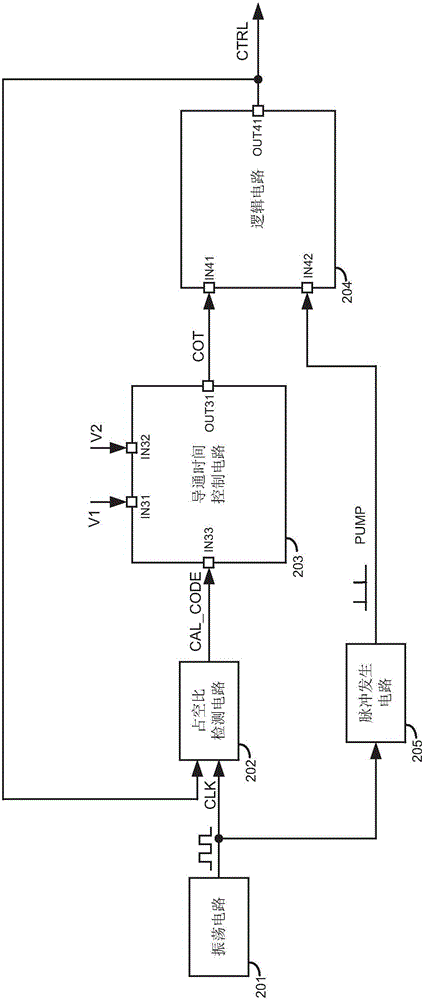
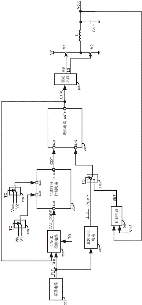
The invention discloses a switching converter for constant turn-on time control as well as a controller, a control method and an automatic calibration method thereof. The switching converter comprises a main transistor, a turn-on time control circuit for determining the turn-on time of the main transistor, and a logic circuit for controlling the main transistor. The automatic calibration method comprises the steps of: generating periodic clock signals with a preset duty cycle; providing a first voltage and a second voltage to the turn-on time control circuit, so that the turn-on time control circuit generates turn-on time control signals based on the first voltage and the second voltage; providing the clock signals and the turn-on time control signals to the logic circuit, so that the logic circuit generates switching control signals based on the clock signals and the turn-on time control signals; comparing the duty cycle of the switching control signals with the duty cycle of the clock signals to generate correction code signals; and adjusting circuit parameters in the turn-on time control circuit based on the correction code signals.

Description

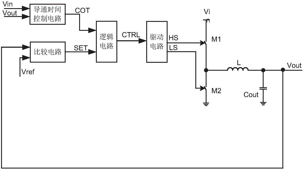
technical field [0001] The invention relates to an electronic circuit, in particular to a switching converter controlled by constant on-time and its controller, control method and automatic calibration method. Background technique [0002] Constant on-time control (COT control, constant on-time control) has been well applied in the power supply field due to its superior load transient response, simple internal structure and smooth operation mode switching. [0003] figure 1 It is a block diagram of an existing synchronous buck converter using constant on-time control, where the on-time control circuit usually generates an on-time control signal COT based on the input voltage Vin and the output voltage Vout to determine the conduction of the upper transistor M1 time. The comparison circuit compares the output voltage Vout with the reference voltage Vref to provide a comparison signal SET. The logic circuit generates a switch control signal CTRL according to the on-time con...

Claims


Application Information

Patent Timeline
Patent Type & Authority Applications(China)
IPC IPC(8): H02M1/088H02M3/158
CPCH02M1/088H02M3/158H02M1/36H03K3/017H03M1/1014H03M1/52H02M1/0025Y02B70/10H03K17/16H03M1/1023H03M1/804H04W76/23H02M1/0032
Inventor 钟昌贤
Owner CHENGDU MONOLITHIC POWER SYST
Why Eureka
Try Eureka