
Clean chemical work station

A workstation and chemical technology, applied in the field of microelectronic process equipment, can solve the problems of less safety and reliability of the purification workbench, gas leakage, etc., and achieve the effects of improving the orderliness of the air flow, preventing the air flow from rebounding, and reducing the cost.

Active Publication Date: 2016-10-05
南通华梦聚氨酯材料有限公司
View PDF7 Cites 3 Cited by
  • Summary
  • Abstract
  • Description
  • Claims
  • Application Information

AI Technical Summary

Problems solved by technology

[0007] However, this kind of purification workbench will inevitably have a small amount of gas leaking from the high-pressure area. When there is high-risk toxic gas, the purification workbench becomes less safe and reliable

Method used


Image

  • Clean chemical work station
  • Clean chemical work station
  • Clean chemical work station

Examples


Embodiment 1

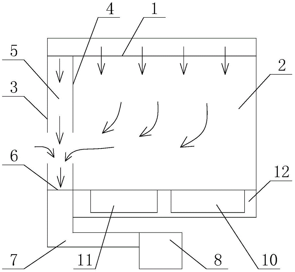
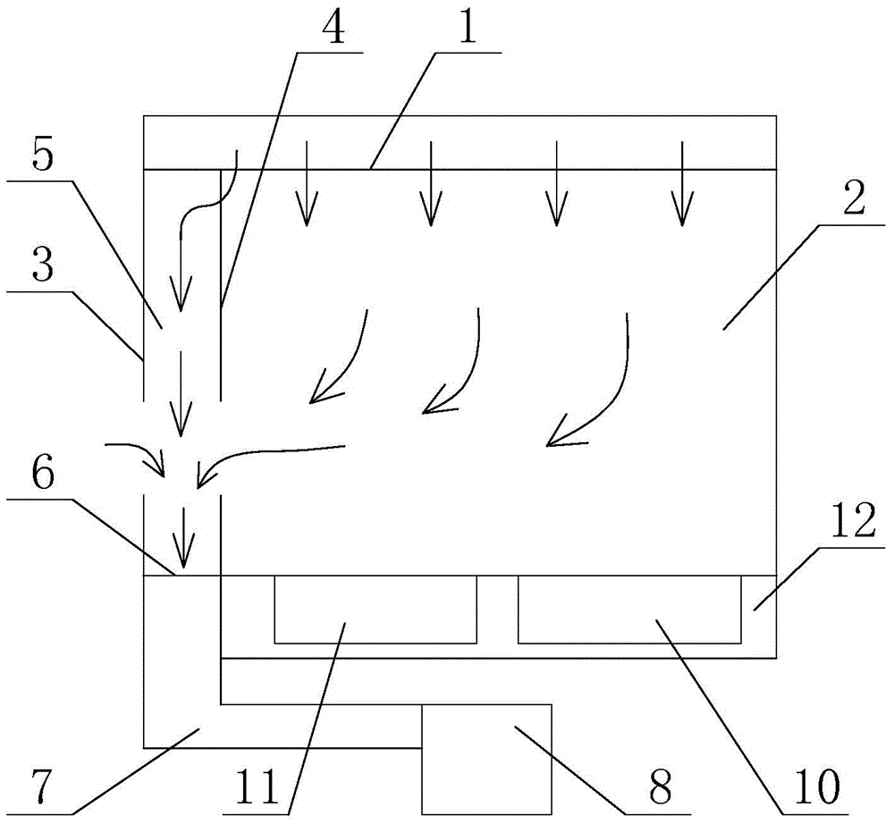
[0028] Such as figure 1 As shown, the present embodiment purifies the chemical workstation, the purification workbench and the water bath heating pool 10 and the cleaning water pool 11 placed inside the purification workbench. Among them, the purification workbench includes an air intake system and an exhaust system. A diffuser plate 1 is provided below the air intake system. A working cavity 2 is located below the diffuser plate 1. A base 12 is provided below the working cavity 2. A water bath heating pool 10 and The cleaning pool 11 is embedded in the base. There is a transparent end plate 2 with an operation hole 9 near the outer end of the working cavity 2 of the staff (see Figure 4 ), the side of the working cavity 2 close to the end plate 3 is a transparent partition 4, and the transparent partition 4 has an operation hole for the staff to extend their hands into the interior of the working cavity for operation (the structure of the partition 4 can be compared with the...

Embodiment 2

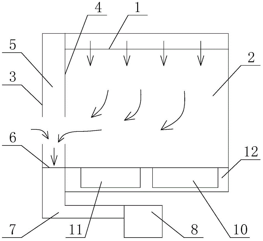
[0034] Such as image 3As mentioned above, the purification chemical workstation in this embodiment is a simplified solution of the purification chemical workstation in Embodiment 1, the specific difference is that no purified air is introduced above the partition of the purification workbench. Specifically, the purification chemical workstation in this embodiment includes a purification workbench and a water bath heating pool 10 and a cleaning water pool 11 placed inside the purification workbench. The purification workbench includes an air intake system and an exhaust system. A diffuser plate 1 is provided below the air intake system. A working chamber 2 is located below the diffuser plate 1 and a base 12 is located below the working chamber. The outer end of the working cavity 2 close to the staff has a transparent end plate 2 with an operation hole 9, and the side of the working cavity 2 close to the end plate 3 is a transparent partition 4, and the transparent partition 4...


PUM


Abstract

The invention relates to a clean chemical work station which includes a clean work bench and a water bath heating tank and a clean water tank which are arranged therein. The clean work station includes a gas inlet system, a gas exhaust system and a work chamber. A transparent end plate, in which an operation hole is formed, is arranged on the outer end of the work chamber. One side, which is closed to the transparent end plate, of the work chamber is a transparent insulation plate. An insulation layer is formed between the transparent end plate and the transparent insulation plate. The gas exhaust system includes a gas exhaust port which is arranged below the insulation layer, and a gas pumping apparatus which is connected to the gas exhaust port through a gas exhaust pipeline. In the invention, the water bath heating tank and the clean water tank are disposed in the clean work bench, so that a clean environment for chemical etching is provided, and meanwhile, volatile gas is prevent from escaping into atmosphere, so that damage of the volatile gas to body during the chemical etching is avoided. A user can carry out work with the clean work bench in a normal environment without any special dust-free room, so that the clean work station can greatly reduce cost and has important significance on scientific research and education.

Description

technical field [0001] The invention relates to a purification chemical workstation, which belongs to the technical field of microelectronic process equipment. Background technique [0002] Chemical etching is a common process step in the solar cell manufacturing process. The exposed silicon wafer is put into an etching solution for etching, and then cleaned with deionized water. Since the microelectronics industry requires a clean environment, chemical etching and cleaning are performed in a clean room. However, for the operators who are also in the clean room, the harmful substances volatilized during the etching process will adversely affect their health. [0003] In industrial production and scientific research, dust-free working environment is required in many places. The purification workbench can provide an effective working environment for these purposes and improve the efficiency of production and scientific research. The inventor imagines that if the chemical pa...

Claims


Application Information

Patent Timeline
Patent Type & Authority Applications(China)
IPC IPC(8): B01L1/04
Inventor 王强邓洁朱海峰
Owner 南通华梦聚氨酯材料有限公司
Learn More