Permanent magnet electric device, an electric car and driving, brake and range increasing method thereof

A technology for electric devices and electric vehicles, which is applied in the deceleration devices of DC motors, electromechanical devices, electric vehicles, etc., can solve the problems of short continuation mileage, unrealistic continuation mileage, and high manufacturing costs.

Inactive Publication Date: 2016-10-05
NANJING MENGQI INTELLIGENT TECH +1
View PDF4 Cites 0 Cited by
  • Summary
  • Abstract
  • Description
  • Claims
  • Application Information

AI Technical Summary

Problems solved by technology

PWQ technology is generally used in control. The main problem of this kind of permanent magnet brushless DC motor is the approximation control of sine wave deformation. Although its power supply is modulated by PWQ technology, the control method is limited by the traditional internal motor. design
[0005] Short mileage is the weakness of electric vehicles at this stage. The industry generally believes that before high-energy batteries enter commercial use, it is unrealistic to increase the mileage of electric vehicles by increasing the number of batteries. Therefore, the current mainstream of the automobile market is to develop a dual-source hybrid of oil and electricity. The design concept of the car is: when the car starts or at low speed, the power of the electric motor is used, and when the car reaches a certain speed threshold, it is converted to use the power of the interna...

Method used


Image

  • Permanent magnet electric device, an electric car and driving, brake and range increasing method thereof
  • Permanent magnet electric device, an electric car and driving, brake and range increasing method thereof
  • Permanent magnet electric device, an electric car and driving, brake and range increasing method thereof

Examples


Embodiment 1

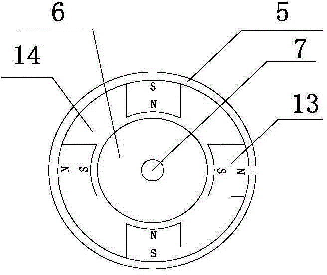
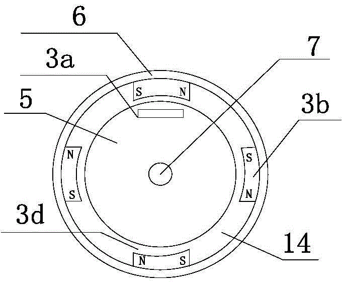
[0094] An electric device and its matching electric two-wheeled vehicle, the motor body of the electric device is arranged on the rear wheel, and its local structure on the vehicle frame 4 is as follows: Figure 10a As shown, the circumference of the wheel is 1000mm, and the battery pack 8 is a 24V12Ah lithium iron phosphate battery installed inside the frame. The fixed body 5 of the electric device is designed as a disk with a fixed shaft outside, and the external mechanical parameters of the fixed shaft are designed with reference to the data of the conventional two-wheeled wheel axle, and are used to replace the conventional two-wheeled wheel shaft for installation; the rotating body 6 of the electric device utilizes A double-annular titanium-aluminum alloy ring with a rotating shaft and an inner circumference of 500 mm (generally referred to as a hub in industry practice), which can be coaxially fitted with the fixed body on the outside of the fixed body of the disc; when t...

Embodiment 2

[0102] The electric device described in embodiment 1 is configured on the front wheel of a tricycle, and the local structure of the vehicle frame 4 is as follows: Figure 10b Shown; The design installation method of the circumference of wheel and swivel, stator unit and rotor unit is similar to embodiment 1, and battery pack 8 selects 48V100Ah lead-acid colloid battery for use, is installed in the battery box inside vehicle frame.

[0103] The outside of the rotating body 6 is provided with a deceleration / torque conversion device 2 composed of several gears, which is installed concentrically with the rotating body, such as Figure 10b As shown in the front wheel of a tricycle, the reduction ratio of the deceleration / torque conversion device is 10:1; the transmission input end of the deceleration / torque conversion device is fixedly connected with the rotating body, and there are several mechanical holes on the outside, and one end of several spokes is perforated and fixed , the...

Embodiment 3

[0109] An electromagnetic braking function is added to the electric device described in Embodiment 1.

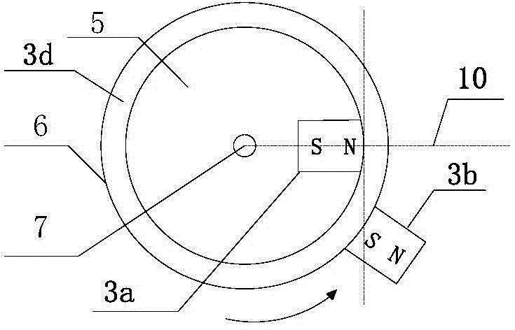
[0110] The electromagnetic braking device 9b is a ten-stage rheostat, and the power supply modulator correspondingly adds a braking signal input terminal 1e to electrically connect the electromagnetic braking device 9b, such as Figure 5c Shown; when the manual control electromagnetic brake device sends a braking signal, the power modulator cuts off T 1 corresponding to the timing current, start T 2 The time domain is energized, and the brake energization time domain is set so that the sensing unit 3c senses the rotor unit 3b around the shaft to 4 degrees to The time period for the 0 position.

[0111] The brake current output by the power modulator corresponds to the ten-level resistance of the electromagnetic braking device 9b, which is set to ten-level intensity, and the output current intensity is set to be: the first level is 5A, the last level is 12A, and the ten-...


PUM

PropertyMeasurementUnit
Diameteraaaaaaaaaa

Abstract

The present invention discloses a permanent magnet electric device, an electric car and a driving, brake and range increasing method thereof. The electronic device comprises a power supply modulator, a driving control device, a fixed body and a rotating body. The rotating body is an annular machinery loop with a rotating shaft is provided with at least four permanent magnet rotor units, having the same direction with the magnetic pole, arranged at intervals; the fixed body is a machinery disc with a fixed shaft and at least provided with a stator unit, wherein the periodical relative air gap between the stator unit and the rotor unit is not larger than 30mm; the electric pole direction of the stator unit is opposite to the magnetic pole moving opposite to the rotor unit; the power supply modulator obtains a user instruction and outputs corresponding time sequence current according to the driving control device/an electromagnetic braking device to allow the electric device to realize driving/braking; and the electric car includes a car frame, a battery pack and at least one wheel and is at least provided with a set of the electric device, and a range increasing system is configured to supply electric energy for a secondary battery pack in a setting logic state.

Description

technical field [0001] The invention relates to the field of electric vehicle and its power source power design, in particular to a mechanical design of an electric device, a sequential current design method for driving current and braking, and a range-extending method for the electric vehicle. Background technique [0002] At present, the electric bicycle market is usually equipped with a motor installed on the wheel shaft. The motor is designed as an outer rotor. The outer rotor is mechanically connected to the rim of the wheel through the spokes, and the wheel is rotated by the torque of the motor. The hot spot in the electric vehicle industry is the development of passenger wheel hub motors, also known as wheel built-in motors. Industry experts generally believe that because the weight of the current hub motor components far exceeds the hub body (generally including hub motors, brake discs, brake calipers, and active suspension motors) , suspension, damping spring, etc.)...

Claims


Application Information

Patent Timeline
IPC IPC(8): H02K11/00H02K21/14H02K7/116H02K29/06H02K7/10H02P6/08H02P6/16H02P3/08
CPCY02T10/64
Inventor 刘粤荣刘通
Owner NANJING MENGQI INTELLIGENT TECH
Why Eureka
Try Eureka