
Self-oscillation DC-DC circuit

A DC-DC, self-oscillating technology, applied to electrical components, adjusting electrical variables, instruments, etc., can solve the problems of increasing chip cost, simultaneous conduction, and high electromagnetic interference EMI, so as to reduce power loss, avoid power loss, and reduce Effects of Electromagnetic Interference

Inactive Publication Date: 2016-10-05
CHENGDU ANALOG CIRCUIT TECH INC
View PDF4 Cites 2 Cited by
  • Summary
  • Abstract
  • Description
  • Claims
  • Application Information

AI Technical Summary

Problems solved by technology

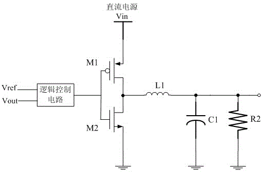
[0005] Since the two switch MOS tubes usually use the same control signal, they are prone to simultaneous conduction, resulting in a large amount of power loss
[0006] (2) In traditional DC-DC circuits, it is usually necessary to use an oscillator to output clock pulse signals and other signals of the same frequency, which undoubtedly increases the package area occupied by the chip, increases the cost of the chip, and also causes a certain amount of power consumption. loss
[0007] (3) The traditional DC-DC circuit structure is complicated, and it will occupy a large package area when the circuit is integrated, increasing the cost of chip production
[0008] (4) Traditional DC-DC circuits have high power consumption, low efficiency, high electromagnetic interference EMI, and some are equipped with EMI processing modules

Method used


Image

  • Self-oscillation DC-DC circuit
  • Self-oscillation DC-DC circuit
  • Self-oscillation DC-DC circuit

Examples


Embodiment 1

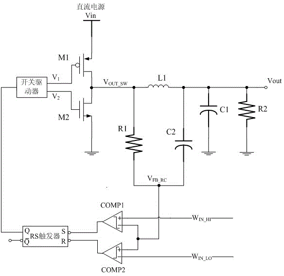
[0049] The non-inverting input terminal of the first comparator COMP1, that is, its first input terminal and the high threshold reference voltage W IN_HI Connection, the inverting input end of the first comparator COMP1 is its second input end and the non-inverting input end of the second comparator COMP2 is its first input end are all connected with the output end of the triangular wave generating circuit, the first comparator COMP1 The output terminal is connected to the input terminal R of the RS flip-flop, that is, its first input terminal, and the inverting input terminal of the second comparator COMP2, that is, its second input terminal is connected to the low threshold reference voltage W IN_LO Connection, the output terminal of the second comparator COMP2 is connected to the input terminal S of the RS flip-flop, that is, its second input terminal, and the output terminal of the RS flip-flop That is, the first output terminal thereof is connected to the input terminal ...

Embodiment 2

[0065] Embodiment 2 is different from Embodiment 1 in that: the output end of the second comparator COMP2 is connected to the input end R of the RS flip-flop, the output end of the first comparator COMP1 is connected to the input end S of the RS flip-flop, and the RS The output terminal Q of the flip-flop is connected to the input terminal of the switch driver, and the output terminal of the RS flip-flop empty link. That is to say, the connection relationship and connection contacts of the window voltage comparator, the triangular wave generating circuit and the switch driver are not changed, only the RS flip-flop is reversed, and then connected to the window voltage comparator and the switch driver respectively. The working principle of the second embodiment can be known in the same way, and will not be repeated here.

[0066] In the present invention, since the internal resistance of the PMOS tube is very small, its internal resistance is negligible relative to the resista...


PUM


Abstract

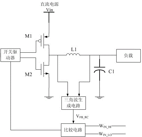
The invention discloses a self-oscillation DC-DC circuit. The source electrode of a switch MOS tube M1 is connected with a DC power supply Vin, the drain electrode of the switch MOS tube M1 and the drain electrode of a switch MOS tube M2 are connected with one end of an energy storing inductor L1, the grid electrode of the switch MOS tube M1 and the grid electrode of the switch MOS tube M2 are connected to two output ends of a switch driver respectively, the source electrode of the switch MOS tube M2 is connected to the ground, the other end of the energy storing inductor L1 is connected with the anode of an energy storing capacitor C1 and a load, the cathode of the energy storing capacitor C1 is connected to the ground, the two input ends of a triangular wave generation circuit are connected to the two ends of the energy storing inductor L1 in parallel, the output end of the triangular wave generation circuit is connected with the source signal input end of a comparison circuit, two window signal input ends of the comparison circuit are connected to the window voltage, and the output end of the comparison circuit is connected with the input end of the switch driver. The self-oscillation DC-DC circuit is characterized by simple structure, self oscillation, free of an amplification circuit, rapid response, low power consumption, low electromagnetic interference and the like.

Description

technical field [0001] The invention relates to the field of electronic circuits, in particular to a self-oscillating DC-DC circuit. Background technique [0002] DC / DC circuit is a switching power supply circuit, which uses the energy storage characteristics of capacitors and inductors to perform high-frequency switching actions through controllable switches (such as MOSFETs, etc.), and stores the input electric energy in capacitors (inductors). When the switch is turned off, the electric energy is released to the load to provide energy for the load. The power or voltage output capability of the DC / DC circuit is related to the duty cycle, which is the ratio of the on-time of the switch to the cycle of the entire switch. [0003] like figure 1 as shown, figure 1 As a traditional step-down DC-DC circuit, this kind of DC-DC circuit generally has the following problems: [0004] (1) In traditional DC-DC circuits, diodes are usually used for rectification, and the forward co...

Claims


Application Information

Patent Timeline
Patent Type & Authority Applications(China)
IPC IPC(8): H02M3/155
Inventor 葛亮宏叶飞何天长况波
Owner CHENGDU ANALOG CIRCUIT TECH INC
Learn More