Row inter-tube falling film melt phase polycondensation reaction method and reactor thereof

A technology of melt polycondensation and reactor, which is applied in the field of falling film melt polycondensation reaction between rows of tubes and its reactor, which can solve the problems of slow inner layer film, affecting product quality, degradation, etc.

Active Publication Date: 2016-10-12
ZHEJIANG SCI-TECH UNIV
View PDF5 Cites 6 Cited by
  • Summary
  • Abstract
  • Description
  • Claims
  • Application Information

AI Technical Summary

Problems solved by technology

Especially when preparing high-viscosity materials, the falling film reactor outside the tube can make the material flow outside the tube by gravity alone, providing a suitable residence time so that the material can fully react, but the complete wall-attached falling film flow will Due to the speed difference between the inner and outer layers of the melt film, the flow rate of the outer layer of the liquid film is fast, while the inner layer of the film

Method used


Image

  • Row inter-tube falling film melt phase polycondensation reaction method and reactor thereof
  • Row inter-tube falling film melt phase polycondensation reaction method and reactor thereof
  • Row inter-tube falling film melt phase polycondensation reaction method and reactor thereof

Examples


Embodiment 1

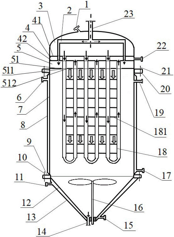
[0027] Embodiment 1, with reference to attached figure 1 , 4 , 5a, 5b, 5c.

[0028] In this embodiment, the straight tubes of U-shaped heat exchange tubes 18 (hereinafter referred to as U-shaped tubes, which include straight tubes on both sides and bent tubes connecting the straight tubes on both sides at the bottom end) adopt straight tubes with constant diameters. .

[0029] A kind of fall-film melt polycondensation reactor between rows of tubes provided by the present embodiment, such as figure 1As shown, it includes a vertical housing 7, a material feed box connected to the upper end of the vertical housing 7 and a bottom shell 12 at the lower end, a heat medium outflow box 4 is arranged above the material feed box 5, and the heat medium flows out A heat medium inflow box 3 is provided on the box 4, a reactor heat medium inlet 1 is arranged on the heat medium inflow box 3, and a reactor heat medium outlet 22 is arranged on the heat medium outflow box 4, arranged in rows...

Embodiment 2

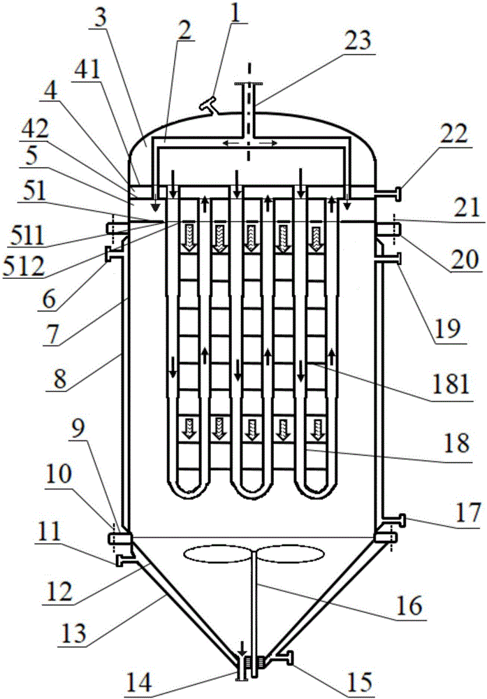
[0048] Embodiment 2, with reference to attached figure 2 , 4 , 5a, 5b, 5c.

[0049] In this embodiment, the straight tube of the U-shaped tube 18 adopts a connected coaxial straight tube with reduced diameter.

[0050] The straight pipe of the U-shaped pipe 18 is reduced in diameter at the same distance below the cloth plate 51 to become a straight pipe with different diameters but continuous communication, coaxial up and down, from the bottom of the cloth plate 51 to the bottom of the U-shaped pipe 18, the pipe diameter slowing shrieking.

[0051] On the reduced-diameter U-shaped pipe, the length of the connecting wire between the straight pipes of each U-shaped pipe is kept equal to the distance between the pipes of the corresponding reduced-diameter straight pipes.

[0052] Other parts and implementation method of this embodiment are the same as embodiment 1, in figure 2 , the reference numerals and figure 1 The same means the same meaning.

Embodiment example 3

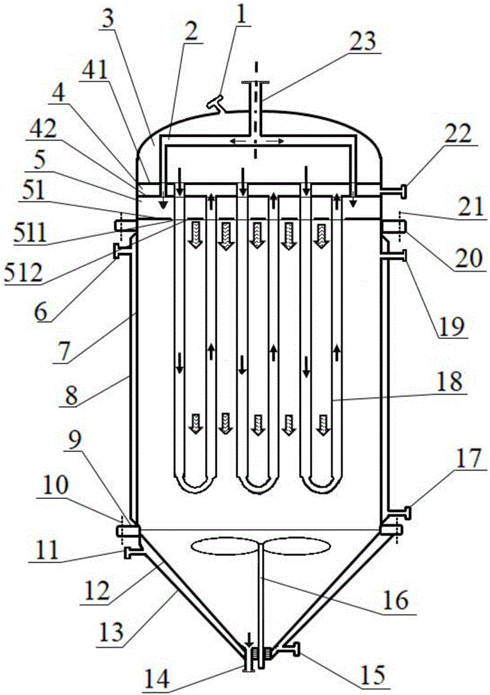
[0053] Implementation case 3, refer to the attached image 3 , 4 , 5a, 5b, 5c.

[0054] In this embodiment, the straight part of the U-shaped tube 18 is a straight tube with a constant diameter, and there is no connecting wire between two straight tubes of the U-shaped tube 18 and between two adjacent straight tubes of the adjacent U-shaped tube 18 in the same row.

[0055] Preferably, the ratio of the distance between the U-shaped tubes 18 to the tube diameter is 0.1-10.

[0056] Other parts and implementation method of this embodiment are the same as embodiment 1, in image 3 , the reference numerals and figure 1 The same means the same meaning.


PUM

PropertyMeasurementUnit
Diameteraaaaaaaaaa
Outer diameteraaaaaaaaaa

Abstract

The invention relates to a row inter-tube falling film melt phase polycondensation reaction method. A melt prepolymer flows downwards from a film distribution plate and holes between tubes, a waterfall falling film flowing is formed between the U-shaped tubes in rows so that a melt phase polycondensation can be performed, and a melt slides down from the tubes, then condensed at the bottom of a reactor and discharged after stirring is performed to be homogenized through a stirrer. The reactor implementing the method is of an overall vertical structure and comprises a shell, a heating medium box at the upper end, a material box connected with the heating medium box, the U-shaped tubes, a bottom shell at the lower end, a stirrer and the like. The U-shaped tubes are perpendicularly suspended and arranged in rows, uniformly penetrate through holes in the film distribution plate, and the ends of the U-shaped tubes and the heating medium box are communicated to allow a heating medium to flow. The reactor has the advantages that the flowing resistance is small, no dead zone is generated, the film forming area is large, the surface updating speed is high, the standing time is uniform and controllable, and flexible production is met. The method is applicable to production of polyethylene glycol terephthalate and other polymers.

Description

technical field [0001] The invention relates to a falling film type melt polycondensation reaction method and melt polycondensation reaction equipment in polymer production. Background technique [0002] Polycondensation reaction is a reversible polymerization reaction that continuously produces small molecular compounds, including polyethylene terephthalate (PET), polytrimethylene terephthalate (PTT), polybutylene terephthalate ( Polymers such as PBT), polyethylene naphthalate (PEN), polyamide (PA) and polycarbonate (PC) are all prepared by polycondensation. The similar feature of this kind of polymer is that in the process of polycondensation reaction, the devolatilization process of eliminating small molecular compounds must be continuously carried out to promote the continuous positive reaction, so the viscosity of the material is extremely high, especially in the late stage of polycondensation, the material The dynamic viscosity will change by an order of magnitude. Th...

Claims


Application Information

Patent Timeline
IPC IPC(8): B01J19/00B01J19/18
CPCB01J19/0013B01J19/18B01J2219/00081
Inventor 陈文兴陈世昌张先明马建平
Owner ZHEJIANG SCI-TECH UNIV
Why Eureka
Try Eureka