Automatic numerical control lathe tailstock control method

A numerical control lathe tailstock and numerically controlled lathe technology are applied in the field of numerically controlled lathes, which can solve the problems that the tailstock of numerically controlled machine tools cannot be automatically fed, the depth of drilling holes cannot be guaranteed, and the processing efficiency is low, so as to improve flexibility and control drilling. Hole depth, the effect of improving the degree of automation

Active Publication Date: 2016-10-12
三星智能科技盐城有限公司
View PDF6 Cites 1 Cited by
  • Summary
  • Abstract
  • Description
  • Claims
  • Application Information

AI Technical Summary

Problems solved by technology

[0002] CNC lathe is one of the most commonly used automatic processing equipment in mechanical cutting. However, the tailstock of general CNC machine tools cannot be fed automatically. Therefore, when performing drilling operations on CNC lathes, only the operating handle of the tailstock can be manually rotated. , time-consuming and labor-intensive, it is difficult to guarantee the drilling depth, and the processing efficiency is low

Method used


Image

  • Automatic numerical control lathe tailstock control method
  • Automatic numerical control lathe tailstock control method
  • Automatic numerical control lathe tailstock control method

Examples


Embodiment Construction

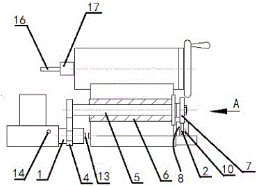
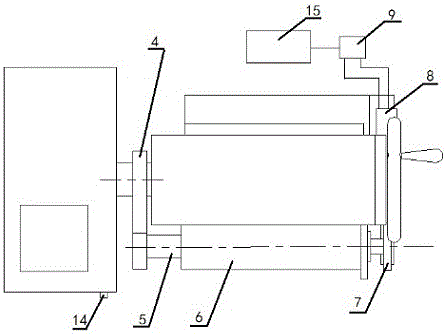
[0020] An automatic control method for a tailstock of a CNC lathe, which uses a cylinder to realize the automatic engagement and disengagement of a saddle and a tailstock of a CNC lathe, and includes a connecting column 1, a rotating arm assembly, a driving assembly and a drill assembly. The middle part of the connecting column 1 is provided with a ring groove 3, the connecting column 1 is fixedly connected with the saddle of the CNC lathe, and a pair of sensors 13 are arranged on the shaft end of the connecting column 1 and the side of the tailstock, and the sensors can be magnetic effect sensors or Hall effect sensors. The sensor can also be a photoelectric sensor.

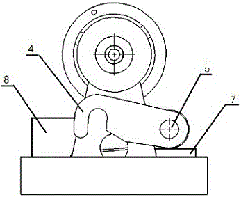
[0021] Described rotating arm assembly comprises rotating arm 4, rotating shaft 5, axle sleeve 6 and bull gear 7, and described axle sleeve 6 is fixed on the front side of CNC lathe tailstock, and described rotating shaft 5 passes through axle sleeve 6, and rotates The front end of the shaft 5 is fixedly connect...


PUM


Abstract

The invention provides an automatic numerical control lathe tailstock control method. A connection device for achieving automatic connection and disconnection between a lathe saddle and a tailstock of a numerical control lathe through an air cylinder is utilized. The connection device comprises a connection pillar, a rotating arm assembly, a drive assembly and a drill bit assembly, the middle of the connection pillar is provided with an annular groove, the shaft end of the connection pillar and the side face of the tailstock are provided with a pair of sensors, the rotating arm assembly comprises a rotating arm, a rotating shaft, a shaft sleeve and a big gear, the shaft sleeve is fixed to the front side face of the tailstock of the numerical control lathe, the rotating shaft penetrates through the shaft sleeve, the front end of the rotating shaft is fixedly connected with the rotating arm, the other end of the rotating shaft is fixedly connected with the big gear, the front end of the rotating arm is provided with a hook portion capable of being clamped into an annular groove, the drive assembly comprises a rack, an air cylinder, a magnetic exchange valve, a rack guide groove, a reset switch and a controller, the controller is mounted in a lathe power distribution cabinet and electrically connected with a numerical control system and the magnetic exchange valve, and the rest switch is mounted in front of the lathe saddle of the numerical control lathe and electrically connected with the controller.

Description

technical field [0001] The application relates to the technical field of numerical control lathes, in particular to an automatic control method for tailstocks of numerical control lathes. Background technique [0002] CNC lathe is one of the most commonly used automatic processing equipment in mechanical cutting. However, the tailstock of general CNC machine tools cannot be fed automatically. Therefore, when performing drilling operations on CNC lathes, only the operating handle of the tailstock can be manually rotated. , Time-consuming and labor-intensive, it is difficult to guarantee the depth of drilling, and the processing efficiency is low. Contents of the invention [0003] Aiming at the existing technical defects, the present invention provides an automatic control method for the tailstock of a CNC lathe, which uses a connecting device that uses a cylinder to realize automatic engagement and disengagement of the saddle and tailstock of a CNC lathe, and has a simple ...

Claims


Application Information

Patent Timeline
Patent Type & Authority Applications(China)
IPC IPC(8): B23B23/00B23B25/06B23Q5/26B23Q5/38B23B43/02
CPCB23B23/00B23B25/06B23B43/02B23Q5/26B23Q5/348B23Q5/385
Inventor 张循环
Owner 三星智能科技盐城有限公司
Why Eureka
Try Eureka