Double-rotor flat assembling movable blade through-flow type hydraulic generator

A hydroelectric generator and tubular technology, applied in hydroelectric power generation, reaction engines, engine components, etc., can solve the problems that the raw materials, wires and parts cannot be used in common, the temperature of the rotor cannot be measured in real time, and the capacity cannot be adjusted at will. , to avoid bearing friction and energy consumption, improve energy conversion efficiency, reduce construction costs and production management costs

Inactive Publication Date: 2016-10-12
郭远军
View PDF0 Cites 0 Cited by
  • Summary
  • Abstract
  • Description
  • Claims
  • Application Information

AI Technical Summary

Problems solved by technology

[0010] Existing tubular water turbines are all connected to the generator through the main shaft, so as to drive the generator rotor to rotate and cut the magnetic force line to generate electricity. The structure of the turbine and the generator requires at least three bearings, and some models also need to use complex structures and expensive bearings. servomotor
[0011] Moreover, the existing hydraulic generators need to design a ventilation system to dissipate heat from the generator, design a seal, and require a cooling water system to dissipate heat from the generator, requiring at least one thrust point, multiple bearings, stators, rotors, and salient poles, which require high material strength , the rotor temperature cannot be measured in real time, and each group of hydro-generators is a customized machine for different terrains, resulting in raw materials, components, wires and parts that cannot be used in common use, and cannot be mass-produced. The series connection structure of the machine and the exciter results in a huge volume and requires a lot of materials, which directly results in high cost
The capacity cannot be adjusted arbitrarily when the shell remains the same

Method used


Image

  • Double-rotor flat assembling movable blade through-flow type hydraulic generator
  • Double-rotor flat assembling movable blade through-flow type hydraulic generator
  • Double-rotor flat assembling movable blade through-flow type hydraulic generator

Examples


Embodiment Construction

[0036] The following will clearly and completely describe the technical solutions in the embodiments of the present invention with reference to the accompanying drawings in the embodiments of the present invention; obviously, the described embodiments are only some, not all, embodiments of the present invention. Based on the embodiments of the present invention, all other embodiments obtained by persons of ordinary skill in the art without making creative efforts belong to the protection scope of the present invention.

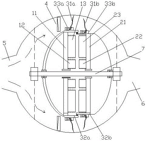
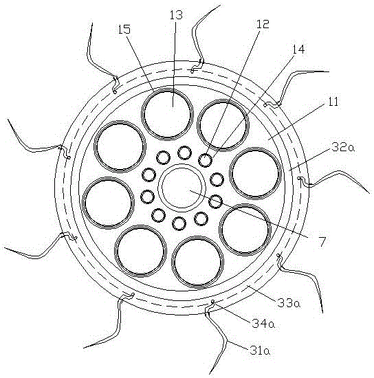
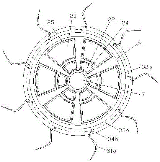
[0037] Option 1 (if figure 1 and figure 2 shown): a double-rotor flat-mounted propeller tubular hydroelectric generator, including an armature rotor mechanism 1, an excitation rotor mechanism 2, a first runner mechanism 3a, a second runner mechanism 3b, a guide vane mechanism 4, The water inlet pipe 5, the draft pipe 6 and the support shaft 7; the armature rotor mechanism 1 and the excitation rotor mechanism 2 are coaxially rotated side by side and installed...


PUM


Abstract

The invention discloses a double-rotor flat assembling movable blade through-flow type hydraulic generator which comprises an armature rotor mechanism, an excitation rotor mechanism, a first turning wheel mechanism, a second turning wheel mechanism, a guide vane mechanism, a water inlet tube, a draft tube and a supporting shaft. The armature rotor mechanism and the excitation rotor mechanism are coaxially and rotationally installed on the supporting shaft in parallel front and back; the circumferential outer diameter part of the armature rotor mechanism is fixedly connected with the first turning wheel mechanism; the circumferential outer diameter part of the excitation rotor mechanism is fixedly connected with the second turning wheel mechanism; the guide vane mechanism is fixedly installed on the front side of the first turning wheel mechanism; the water inlet tube is arranged in front of the guide vane mechanism; and the draft tube is located on the rear side of the second turning wheel mechanism. The double-rotor flat assembling movable blade through-flow type hydraulic generator is free of ventilation systems or cooling water systems, high in power generation efficiency, good in universality, small in size, low in requirement for materials and long in service life, and a few consumables are needed.

Description

technical field [0001] The invention relates to the field of hydroelectric equipment, in particular to a double-rotor flat-mounted propeller tubular hydroelectric generator. Background technique [0002] According to the working principle, water turbines can be divided into two categories: impact turbines and impact turbines. [0003] The runner of the impact turbine rotates under the impact of the water flow, and the pressure of the water flow remains unchanged during the working process, mainly due to the conversion of kinetic energy; [0004] The runner of the impact turbine is rotated by the reaction force of the water flow in the water, and the pressure energy and kinetic energy of the water flow are changed during the working process, but mainly the conversion of the pressure energy. [0005] Pelton turbines can be divided into two types according to the flow direction of the water flow: the cutting type (also known as the water bucket type) and the oblique type. [...

Claims


Application Information

Patent Timeline
Patent Type & Authority Applications(China)
IPC IPC(8): F03B13/00F03B3/06F03B3/14H02K16/00H02K7/18H02K7/20H02K1/22H02K11/25
CPCF03B3/06F03B3/126F03B3/145F03B13/00F05B2220/7066H02K1/22H02K7/1823H02K7/20H02K16/005Y02E10/20
Inventor 郭远军
Owner 郭远军
Why Eureka
Try Eureka