Surface acoustic wave controlled shape memory alloy microvalve and control method thereof

A memory alloy, surface acoustic wave technology, applied in valve details, valve device, valve operation/release device, etc., can solve the problems of aluminum wire current, difficult circuit, difficult to apply piezoelectric microcurrent device, etc. Integrated, simple structure, small volume effect

Inactive Publication Date: 2016-10-12
CHANGZHOU INST OF TECH
View PDF6 Cites 6 Cited by
  • Summary
  • Abstract
  • Description
  • Claims
  • Application Information

AI Technical Summary

Problems solved by technology

Due to the generation of sufficient Joule heat, the current generated by the aluminum wire is required to be large, so it is difficult to be compatible with external circuits, and it is also difficult to apply to piezoelectric microcurrent devices, which needs to be improved

Method used


Image

  • Surface acoustic wave controlled shape memory alloy microvalve and control method thereof

Examples


Embodiment 1

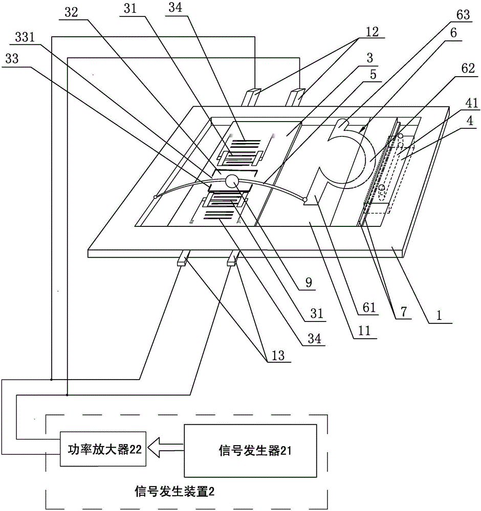
[0035] A kind of surface acoustic wave control shape memory alloy microvalve that present embodiment proposes, such as figure 1 As shown, it includes a PCB board 1, a signal generating device 2 for generating RF electrical signals, a piezoelectric substrate 3, a PDMS solidified body 4 with a microchannel 41, a slightly bent shape memory alloy wire 5 at room temperature, and a convex Out of the rigid bending bar 6 of the extruded part 62, an area of ​​the PCB board 1 (generally the middle area) is hollowed out to form an installation cavity 11, and the piezoelectric substrate 3 is embedded between the two side walls of the installation cavity 11 , the upper surface of the piezoelectric substrate 3 is a working surface, and the working surface of the piezoelectric substrate 3 is provided with two symmetrical interdigital transducers 31 for exciting surface acoustic waves, and the two interdigital transducers 31 They are respectively electrically connected to the signal generatin...

Embodiment 2

[0048] This embodiment proposes the control method of the shape memory alloy microvalve controlled by the surface acoustic wave of embodiment 1, which includes the following steps:

[0049] ① Place the micro-liquid of paraffin oil on the propagation path of the surface acoustic wave.

[0050] ② When the signal generator and power amplifier are not activated, the shape memory alloy microvalve is in the open state, and the digital microfluidics can be transported through the microchannels in the PDMS solidified body under the action of an external injector.

[0051] The control process of the shape memory alloy microvalve from the open state to the closed state is: start the signal generator and the power amplifier; the signal generator outputs the RF electric signal, and transmits the RF electric signal to the power amplifier; the amplified RF electric signal output by the power amplifier Loaded on two interdigital transducers, the power of the RF electrical signal is 31-33 dBm...


PUM


Abstract

The invention discloses a surface acoustic wave controlled shape memory alloy microvalve and a control method thereof. The microvalve comprises a PCB with a mounting cavity, a signal generation device, a piezoelectric substrate embedded between two side cavity walls of the mounting cavity, a PDMS freezing body connected to a second end cavity wall of the mounting cavity and provided with a microchannel, a shape memory alloy wire slightly bent, and a rigid bent strip; two symmetric interdigital transducers are arranged on the working surface of the piezoelectric substrate; the shape memory alloy wire is transversely spanned on a surface acoustic wave propagation path between the two inerdigital transducers, and one section is covered by paraffin oil microliquid; one end of the shape memory alloy wire is connected with a first end cavity wall of the mounting cavity; one end of the rigid bent strip is connected with the other end of the shape memory alloy wire, and the other end is connected with any one side cavity wall of the mounting cavity; and a convex extrusion part of the rigid bent strip is aligned to the other side wall of the PDMS freezing body. The microvalve has the advantages of simple structure, small size, easy to integrate and capable of being applied to a piezoelectric microflow chip for microflow control operation.

Description

technical field [0001] The invention relates to a microvalve for controlling microfluid transport in a microfluidic chip and its control technology, in particular to a shape memory alloy microvalve controlled by surface acoustic waves and a control method thereof. Background technique [0002] Microfluidic chip is a technology that integrates conventional biochemical analysis operation units on a substrate of several square centimeters to complete biochemical analysis or biochemical detection. Because the microfluidic chip greatly reduces the size of the analysis operation unit, reduces the reagents used in the microfluidic analysis, shortens the analysis time, and facilitates the intelligence and automation of the analysis operation, therefore, the microfluidic chip has achieved rapid development. , and has been widely used in DNA sequencing, protein analysis, single cell analysis, drug detection and food safety and other fields. [0003] Microvalve is an indispensable uni...

Claims


Application Information

Patent Timeline
Patent Type & Authority Applications(China)
IPC IPC(8): F16K99/00F16K31/70
CPCF16K99/0038
Inventor 章安良董良威张小权胡文艳
Owner CHANGZHOU INST OF TECH
Why Eureka
Try Eureka