Loop heat tube condenser applicable to arrangement in circular ring-shaped chamber body

A loop heat pipe and condenser technology, which is applied in the structural design of separate heat pipe condensers and the field of loop heat pipe condensers, can solve the problems of inconvenient liquid outflow, long distance, small filling rate, etc., and achieve convenient mass production and assembly, reduce thermal resistance, and arrange the best effect

Active Publication Date: 2016-10-12
CHINA ACAD OF AEROSPACE AERODYNAMICS
View PDF6 Cites 17 Cited by
  • Summary
  • Abstract
  • Description
  • Claims
  • Application Information

AI Technical Summary

Problems solved by technology

The deficiencies of the condenser of the separated heat pipe heat exchanger mentioned in the above literature can be summed up in several aspects: (1) From the perspective of the falling film of working fluid condensation, the condensation pipes are arranged vertically, and in the entire condensation pipe, when the internal steam condenses , the condensed liquid film flows down along the inner wall surface, and the average thickness of the formed falling liquid film in the axial direction is too large. The structure of the regular cube cannot meet the needs of the circular space arrangement; (3) the liquid header of the condensing pipe is arranged horizontally. If the filling rate of the separated heat pipe is small, or even too small to fill the condensing pipe header, it is inconvenient outflow of liquid, etc.

Method used


Image

  • Loop heat tube condenser applicable to arrangement in circular ring-shaped chamber body
  • Loop heat tube condenser applicable to arrangement in circular ring-shaped chamber body
  • Loop heat tube condenser applicable to arrangement in circular ring-shaped chamber body

Examples


Embodiment Construction

[0037] Below in conjunction with accompanying drawing and specific embodiment the present invention is described in further detail:

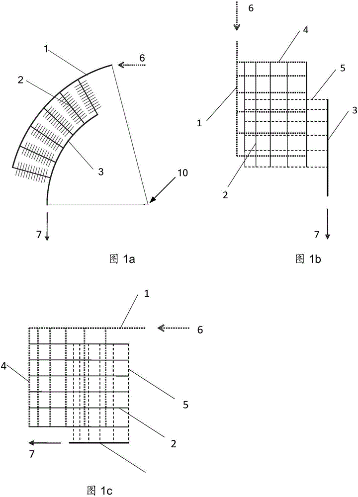
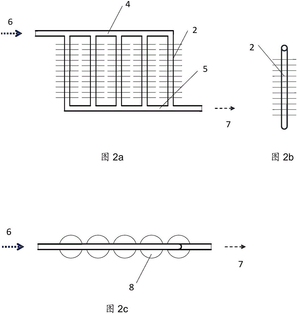
[0038] Such as figure 1 Shown are three views of the condenser of the present invention suitable for the loop heat pipe of the annular cavity, wherein figure 1 a is the front view, figure 1 b is a side view, figure 1 c is a top view; figure 2 Shown is a three-sided view of the condenser tube assembly in the condenser of the loop heat pipe suitable for the circular cavity of the present invention, wherein figure 2 a is the front view, figure 2 b is a side view, figure 2 c is a top view.

[0039] The axis of the circular cavity in the present invention is a horizontal axis, which is parallel to the ground. The condenser suitable for the loop heat pipe of the circular cavity includes several condenser tube assemblies, arc-shaped steam header 1 and arc-shaped liquid header 3, such as figure 2 As shown, each condensing tube assembly incl...


PUM


Abstract

The invention relates to a loop heat tube condenser applicable to arrangement in a circular ring-shaped chamber body. The condenser comprises a plurality of condensing tube components, circular arc-shaped steam headers and circular arc-shaped liquid headers; each condensing tube component comprises n condensing tubes, one straight steam header and one straight liquid header; the n condensing tubes are equal in length and are arranged in parallel; the straight steam headers communicate with one end of each of the n condensing tubes; the straight liquid headers communicate with the other end of each of the n condensing tubes; the condensing tube components are arranged around the horizontal axis of the circular ring-shaped chamber body so that all axes of the n condensing tubes in each condensing tube component point to the axis of the circular ring-shaped chamber body; the straight steam headers in the condensing tube components can communicate with one another through the circular arc-shaped steam headers; the straight liquid headers in the condensing tube components can communicate with one another through the circular arc-shaped liquid headers; the condenser has the advantages of reducing heat resistance, remarkably improving the heat exchange capability, being adaptive to arrangement in an upper space of a horizontal annular chamber, fully utilizing the space of a circular ring-shaped columnar chamber body and realizing high performance and compactness.

Description

technical field [0001] The invention belongs to the technical field of separated heat pipes in engineering thermophysics and heat pipe disciplines, and relates to a structural design of a separated heat pipe condenser, in particular to a condenser suitable for loop heat pipes arranged in a ring cavity. Background technique [0002] The heat pipe is a high-performance heat transfer element, which is a device that continuously transfers heat from the heat source to the heat sink by the evaporation, condensation and reflow of the internal working medium (working fluid). Heat pipes are used in a wide range of applications. With the development of technology, the demand for heat pipes continues to grow. [0003] The structure of the heat pipe is various, and the split heat pipe is a kind of heat pipe. Separate Type Heat Pipe (STHP) is generally composed of evaporator, condenser, steam pipe and liquid pipe. Condenser design and fabrication methods are a key to achieving the desi...

Claims


Application Information

Patent Timeline
Patent Type & Authority Applications(China)
IPC IPC(8): F28D15/02
CPCF28D15/0266
Inventor 曲伟李炜俞继军
Owner CHINA ACAD OF AEROSPACE AERODYNAMICS
Why Eureka
Try Eureka