Sewage treatment control system

A control system and sewage treatment technology, which is applied in water/sewage multi-stage treatment, water/sludge/sewage treatment, flocculation/sedimentation water/sewage treatment, etc. It can solve fouling, troublesome disassembly and maintenance, light transmittance and Reduced photosensitivity and other issues, to achieve good control effect, good control effect, and good stability

Active Publication Date: 2016-10-12
宣尧杭
View PDF6 Cites 6 Cited by
  • Summary
  • Abstract
  • Description
  • Claims
  • Application Information

AI Technical Summary

Problems solved by technology

However, considering that when the detection box disclosed in CN104034702A is detected, the printing and dyeing wastewater is easy to contaminate the surface of the light source and the light sensing element, resulting in a double decline in light transmittance and light sensitivity. The performance is not very good, and there are man

Method used


Image

  • Sewage treatment control system
  • Sewage treatment control system
  • Sewage treatment control system

Examples


Embodiment 1

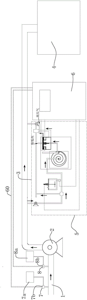
[0050] Such as figure 1 A treatment device for the treatment of printing and dyeing wastewater is shown, which uses a new detection method to detect whether the printing and dyeing wastewater is turbid, and uses the light transmittance index of the treated supernatant as a control point, so the present invention The existing process is improved, and the control system is well structured on the basis of the new process.

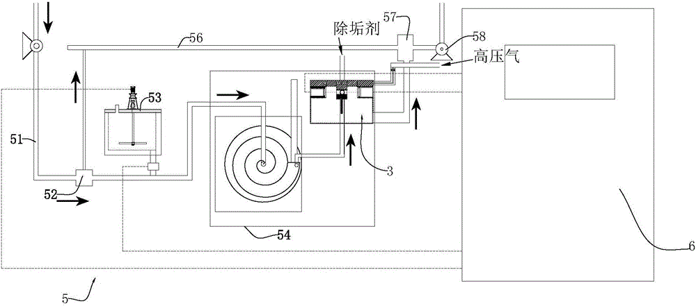
[0051] see Figure 1-15 As shown, the sewage treatment control system includes a water inlet pipe section 1, a decolorizing agent adding device 7, a coagulation aid adding device 8, a sewage pump 2, a water delivery pipeline, a sampling detection device 5 for detecting wastewater treatment indicators, a control box 6 and Sedimentation tank 4. The water inlet pipe section 1 is connected to the water delivery pipe through the sewage pump 2, and the end of the water delivery pipe is connected to the sedimentation tank 4. The arrow in the figure points to the fl...

Embodiment 2

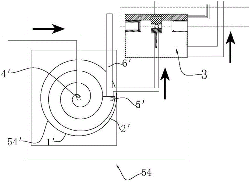
[0079] The difference between this embodiment and embodiment 1 is that this embodiment adopts another settling device, such as Figure 16 As shown, the settling device consists of a rectangular box 10' and a plurality of baffles 20' interlaced and fixed on the inner walls of both sides of the rectangular box 10'. One end of the rectangular box 10' is provided with a water inlet pipe 40'. The rectangular box The bottom of the other end of the 10' is provided with a sedimentation outlet 60', and a supernatant outlet 50' is opened on the top wall near the other end of the rectangular box 10', and the supernatant outlet 50' is connected to the The water inlet pipe 330 in the light transmittance detector 3 of the light transmittance of the printing and dyeing wastewater supernatant. The rest are repeated in Example 1, and will not be described in detail.


PUM


Abstract

The invention relates to a treatment control system for physicochemical treatment of printing and dyeing sewage. The sewage treatment control system comprises a water inlet pipe section, a decolorizer adding device, a coagulant aid adding device, a sewage pump, a water supply pipeline, a sampling detection device for detecting sewage treatment indexes, a control box and a sedimentation tank, wherein the sampling detection device comprises a sampling water inlet pipe, a buffer filter for removing impurities in the printing and dyeing sewage and a detecting box for detecting the light transmittance of the printing and dyeing sewage; the detecting box comprises a box body, as well as a sedimentation device and a light transmittance detector which are connected with the sampling water inlet pipe in sequence, and the light transmittance detector is used for detecting the light transmittance of a supernate of the printing and dyeing sewage; the sedimentation device and the light transmittance detector are both arranged in the box body; the light transmittance detector comprises a casing, a light source, a light-sensitive receiver, and a multi-way flowing passage for a water sample to flow. The sampling detection is adopted and amplified to the whole system, so that not only can the system be better controlled, but also flocculation of the printing and dyeing sewage can be stable and full in the whole technological process.

Description

technical field [0001] The invention belongs to the field of sewage treatment, in particular to a treatment control system for physical and chemical treatment of printing and dyeing sewage. Background technique [0002] China is the world's largest producer and exporter of textiles and clothing, so the printing and dyeing industry is closely related to it, and the wastewater discharge of the printing and dyeing industry is one of the key industries that cause water pollution in my country. Compared with other industries, printing and dyeing wastewater has a large amount of wastewater discharge , deep color, high content of refractory organic matter, unstable water quality and so on. [0003] For the treatment of printing and dyeing wastewater, the existing treatment technologies mainly treat printing and dyeing wastewater through physical and chemical treatment and biochemical treatment in order, so as to degrade harmful substances and meet the discharge standards. For the c...

Claims


Application Information

Patent Timeline
IPC IPC(8): G01N21/59C02F9/04C02F103/30
CPCC02F1/52C02F5/00C02F9/00C02F2103/30G01N21/59
Inventor 宣尧杭
Owner 宣尧杭
Why Eureka
Try Eureka