Current detector
A current detector, current technology, applied in the direction of only measuring current, voltage/current isolation, measuring current/voltage, etc., to achieve the effect of eliminating hysteresis and simple structure
- Summary
- Abstract
- Description
- Claims
- Application Information
AI Technical Summary
Problems solved by technology
Method used
Image
Examples
no. 1 Embodiment approach
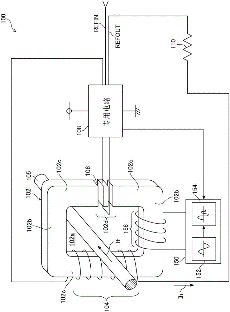
[0044] figure 1 It is a schematic diagram showing the structure of the current detector 100 of the first embodiment. Hereinafter, the structure of the current detector 100 will be described.
[0045] [Magnetic core]
[0046] The current detector 100 includes, for example, a magnetic core 102 made of Permalloy as a material, and the magnetic core 102 as a whole has an approximately angular ring shape. A substantially rectangular current conducting portion 102a is formed inside the magnetic core 102 (the inner circumference of the ring), and a conductor 105 (primary winding) such as a bus bar is inserted into the current conducting portion 102a. The current detector 100 uses the current passing through the conductor 105 as a detection target, and arranges the magnetic core 102 in a ring shape along the circumferential direction of the magnetic field generated when the detected current (If) flows in the conductor 105. In addition, when the detected current (If) is a relatively low l...
Embodiment
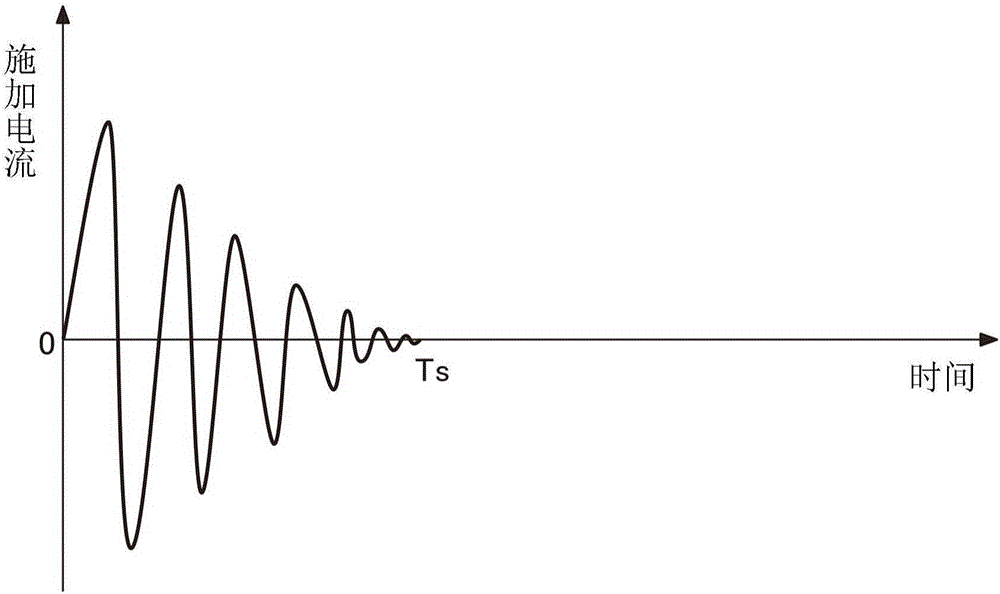
[0116] According to the test results sampled using the above current detector, in figure 1 In the servo-type current detector 100 of the first embodiment shown, a hysteresis removal test was actually performed. The purpose of this test is to cut off the power of the system (such as a refrigerator) that actually uses the current detector 100. When a DC current 10 times the rated value is passed through the conductor 105, the demagnetization circuit 150 is used to remove the magnetic field. The residual hysteresis in the bulk core 102.
[0117] [Theoretical speculation]
[0118] Here, before the actual test, based on the characteristics of the raw material of the magnetic core 102 and the dedicated circuit 108 (discrete product), the following theoretical estimation holds.
[0119] (a) Bias voltage (VOFFSET)=2.5V, rated current If=7A
[0120] (b) The above error = ±20mV
[0121] (c) Current value equivalent to hysteresis (calculated value): According to the formula of Ipp=Vh / Vgain·If, 2...
no. 2 Embodiment approach
[0137] Picture 9 It is a schematic diagram showing the structure of the current detector 200 of the second embodiment. In addition, here, regarding matters common to the first embodiment, including the drawings, common symbols are given, and overlapping descriptions are omitted. Hereinafter, the current detector 200 of the second embodiment will be described centering on the differences from the first embodiment.
[0138] In the second embodiment, the degaussing coil is not wound around the magnetic core 102, and the degaussing circuit 150 is connected in parallel with the secondary winding 104 via a capacitor 158. Therefore, in the second embodiment, the secondary winding 104 can also be used for the purpose of removing hysteresis, and the amount of winding usage can be reduced accordingly.
[0139] In the second embodiment, the degaussing circuit 150 is connected to the feedback coil 104 via the capacitor 158, and after removing the hysteresis of the magnetic core 102 by the de...
PUM
 Abstract
Description
Claims
Application Information
 - R&D
- Intellectual Property
- Life Sciences
- Materials
- Tech Scout
- Unparalleled Data Quality
- Higher Quality Content
- 60% Fewer Hallucinations
Browse by: Latest US Patents, China's latest patents, Technical Efficacy Thesaurus, Application Domain, Technology Topic, Popular Technical Reports.
© 2025 PatSnap. All rights reserved.Legal|Privacy policy|Modern Slavery Act Transparency Statement|Sitemap|About US| Contact US: help@patsnap.com


