
Adaptive smart synchronous high-speed switching device

A high-speed switching and self-adaptive technology, applied in high-voltage/high-current switches, electric switches, high-voltage air circuit breakers, etc., can solve the problems of large dispersion of three-phase action time, economic loss of enterprises, and difficulties in switching off and on, achieving Guarantee the effect of anti-interference ability and accuracy

Active Publication Date: 2016-10-12
ANHUI HEKAI ELECTRICAL TECH CO LTD
View PDF6 Cites 16 Cited by
  • Summary
  • Abstract
  • Description
  • Claims
  • Application Information

AI Technical Summary

Problems solved by technology

The completion time of this process is about 70-100ms. During this period, there will be a period of "voltage sag" in the system voltage, which will cause the low-voltage protection of the internal equipment of the system to operate and cause a large-scale equipment power outage, which will bring huge losses to the enterprise. economic loss
[0003] In addition, the three-phase action of the operating mechanism of the traditional vacuum switch is linked. When the action is to be completed, the three-phase mechanism completes the opening and closing action at the same time, but the dispersion of the three-phase action time is large, which leads to When the electrical equipment is put into operation, a very large inrush current will be generated due to the different electrical angles of the three-phase voltages, making it difficult to cooperate with protection. switch breaking presents difficulties and may cause high magnitude operating overvoltages

Method used


Image

  • Adaptive smart synchronous high-speed switching device

Examples


Embodiment Construction

[0021] In order to make the technical means, creative features, goals and effects achieved by the present invention easy to understand, the present invention will be further described below in conjunction with specific illustrations.

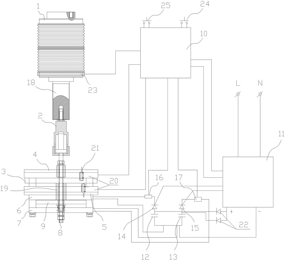
[0022] Such as figure 1 As shown, an adaptive intelligent synchronous high-speed switching device includes a vacuum interrupter 1, a buffer 2, a suction plate 3, an upper yoke 4, a lower yoke 5, an opening coil 6, a closing coil 7, and a center shaft Rod 8, eddy current disk 9, control template 10, fast charging switching power supply module 11, opening capacitor bank 12, closing capacitor bank 13, opening thyristor 14, closing thyristor 15, opening adaptive variable impedance Device 16, closing adaptive variable impedance device 17;

[0023] The moving contact rod 18 on the vacuum interrupter 1 is connected with the buffer 2, and the buffer 2 is connected with the central shaft rod 8, and the central shaft rod 8 is respectively connected with ...


PUM


Abstract

The invention provides an adaptive smart synchronous high-speed switching device. The amplitude, phase angle and zero-crossing point during short circuit can be calculated through current and voltage parameters when a sampling system is short-circuited. Balanced dynamic control of coil driving magnetic flux during a moving transient process is realized, the opening speed of the switch is adjusted automatically according to the short circuit state to satisfy requirements of different short circuit states on opening time. A Rogowski coil on a vacuum circuit breaker explosion chamber mounting base conducts sampling, monitoring and controlling of a current loop, and smart control and phase-splitting control of the switch and synchronous switching are realized.

Description

technical field [0001] The invention relates to the technical field of switching equipment, in particular to an adaptive intelligent synchronous high-speed switching device. Background technique [0002] At present, the opening time of the traditional vacuum switch is 30-50ms, and the closing time is 40-60ms. In order for the switch to operate accurately when the line fails, it must be equipped with a special microcomputer comprehensive protection device (referred to as comprehensive protection device). ), through comprehensive protection sampling current and voltage signals and making judgments to send action signals, so that the vacuum switch completes the opening or closing command and process. The completion time of this process is about 70-100ms. During this period, there will be a period of "voltage sag" in the system voltage, which will cause the low-voltage protection of the internal equipment of the system to operate and cause a large-scale equipment power outage, w...

Claims


Application Information

Patent Timeline
IPC IPC(8): H01H33/664H01H33/666H01H33/02
CPCH01H33/022H01H33/027H01H33/664H01H33/6661
Inventor 李俭华
Owner ANHUI HEKAI ELECTRICAL TECH CO LTD
Learn More