Sputtering target and binding method thereof

A sputtering target and sputtering coating technology, which is applied in the field of sputtering targets, can solve the problems that the backplane components are difficult to be recycled, and achieve the effects of recycling, reducing the use content, and cleaning the surface

Inactive Publication Date: 2016-10-19
HANERGY CO INNO MOBILE ENERGY INVESTMENT CO LTD
View PDF6 Cites 5 Cited by
  • Summary
  • Abstract
  • Description
  • Claims
  • Application Information

AI Technical Summary

Problems solved by technology

However, when epoxy resin glue is used to fix the target material and the backplane assembly, since the epoxy resin glue is not easy to be removed on the backplane assembly, this binding method makes it difficult to recycle the backplane assembly

Method used


Image

  • Sputtering target and binding method thereof
  • Sputtering target and binding method thereof

Examples


Embodiment 1

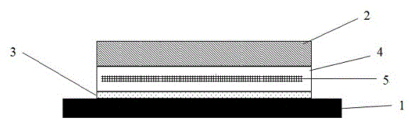
[0026] This embodiment provides a sputtering target, such as figure 1 shown. The backplane component 1 is a copper alloy material, on which a metal indium layer 3 is applied. A conductive adhesive layer 4 is stacked on the metal indium layer, and a non-magnetic metal mesh 5 is arranged in the conductive adhesive layer 4. The non-magnetic metal mesh 5 is a copper mesh, and the target material 2 is bonded on the conductive adhesive layer.

[0027] The binding method is carried out as follows: First, place the copper alloy backplane assembly on the heating table, place an indium block within the welding surface of the backplane assembly, and the welding area is 250cm 2 , the amount of metal indium applied is 5g, the copper alloy backplane is heated to 170°C, and after the indium block is melted, the metal indium is infiltrated onto the surface of the backplane component by using an ultrasonic back-indium equipment.

[0028] Subsequently, use a scraper to scrape the metal indium...

Embodiment 2

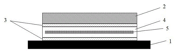
[0032] This embodiment provides a sputtering target, such as figure 2 shown. The backplane component 1 is a copper alloy material, on which a metal indium layer 3 is applied. A conductive adhesive layer 4 is stacked on the metal indium layer, and a non-magnetic metal mesh 5 is arranged in the conductive adhesive layer 4. The non-magnetic metal mesh 5 adopts a copper mesh, and a target material 2 is bonded to the conductive adhesive layer. A layer of metal indium layer 3 is applied on the soldering surface.

[0033] The binding method is carried out according to the following steps: the binding method includes the following steps: first, place the copper alloy backplane assembly on the heating table, place an indium block within the welding surface range of the backplane assembly, and the welding area is 250cm 2 , the amount of metal indium applied is 12.5g, the copper alloy backplane is heated to 190°C, and after the metal indium block is melted, the metal indium is infiltr...


PUM

PropertyMeasurementUnit
thicknessaaaaaaaaaa
tensile strengthaaaaaaaaaa

Abstract

The invention relates to a sputtering target and a binding method thereof. A layer of indium is infiltrated on a solder side of a backboard component of the sputtering target material, and a binder containing conductive particles is used for binding a target material and the backboard component together. The low melting point characteristic of indium is used, so that during unbinding, mutual separation of the target material, the conductive binder and the backboard component is easy. A metal mesh is arranged in the conductive binder, and during unbinding, the conductive binder is attached to the metal mesh, so that after recovery, the surface of the backboard component does not have conductive binder residues.

Description

technical field [0001] The invention belongs to the field of sputtering targets, and in particular relates to a sputtering target and a binding method thereof. Background technique [0002] Sputtering targets are widely used in high-tech industries such as integrated circuits, flat-panel displays, and solar thin-film batteries. With the continuous increase in the size of the sputtering substrate and the application of new technologies and processes, the requirements for the purity, microstructure and connection between the target and the backplane of the sputtering target are also getting higher and higher. [0003] In the sputtering process, the target assembly, as the cathode, should first have excellent electrical conductivity. At the same time, in order to discharge the heat generated by high-energy ions bombarding the surface of the target at high speed, the target assembly should also have excellent thermal conductivity. Therefore, the connection between the target an...

Claims


Application Information

Patent Timeline
Patent Type & Authority Applications(China)
IPC IPC(8): C23C14/34
Inventor 祝令建王波吴国发
Owner HANERGY CO INNO MOBILE ENERGY INVESTMENT CO LTD
Why Eureka
Try Eureka