
Dispersion fiber for high-power transmission with quartz cladding and manufacturing method thereof

A technology of silica cladding and dispersion optical fiber, applied in cladding optical fiber, multi-layer core/cladding optical fiber, manufacturing tools, etc., can solve the problems of poor heat resistance, low transmittance of polymer materials, color conversion, etc. Achieve the effect of improving stability and reliability, solving the problem of color conversion, and reducing the change of scattering loss

Active Publication Date: 2019-02-26
WUHAN POST & TELECOMM RES INST CO LTD +1
View PDF4 Cites 0 Cited by
  • Summary
  • Abstract
  • Description
  • Claims
  • Application Information

AI Technical Summary

Problems solved by technology

[0004] In the existing dispersion optical fiber, the scattering cladding is realized by polymer materials combined with inorganic scattering agents. Due to the low transmittance and poor heat resistance of polymer materials, the scattering effect is poor, and the stability and service life under high power Difference
On the other hand, since the waveguide structure is a step structure, the adjustment of the scattering loss is basically adjusted by the concentration of the dispersant in the scattering cladding, and the uniform dispersion and concentration of the dispersant are not easy to control, so batch consistency and manufacturing are difficult.
In addition, the wavelength of fiber scattered light is usually determined by the light pumped into the diffuse fiber, so if white light is required, it is usually necessary to pump mixed wavelength light at the end face as a white light source, and high-power white light sources are very expensive and unstable. And because the existing dispersion fiber only scatter light, without doping other ions to convert the wavelength, there is a problem of color conversion

Method used

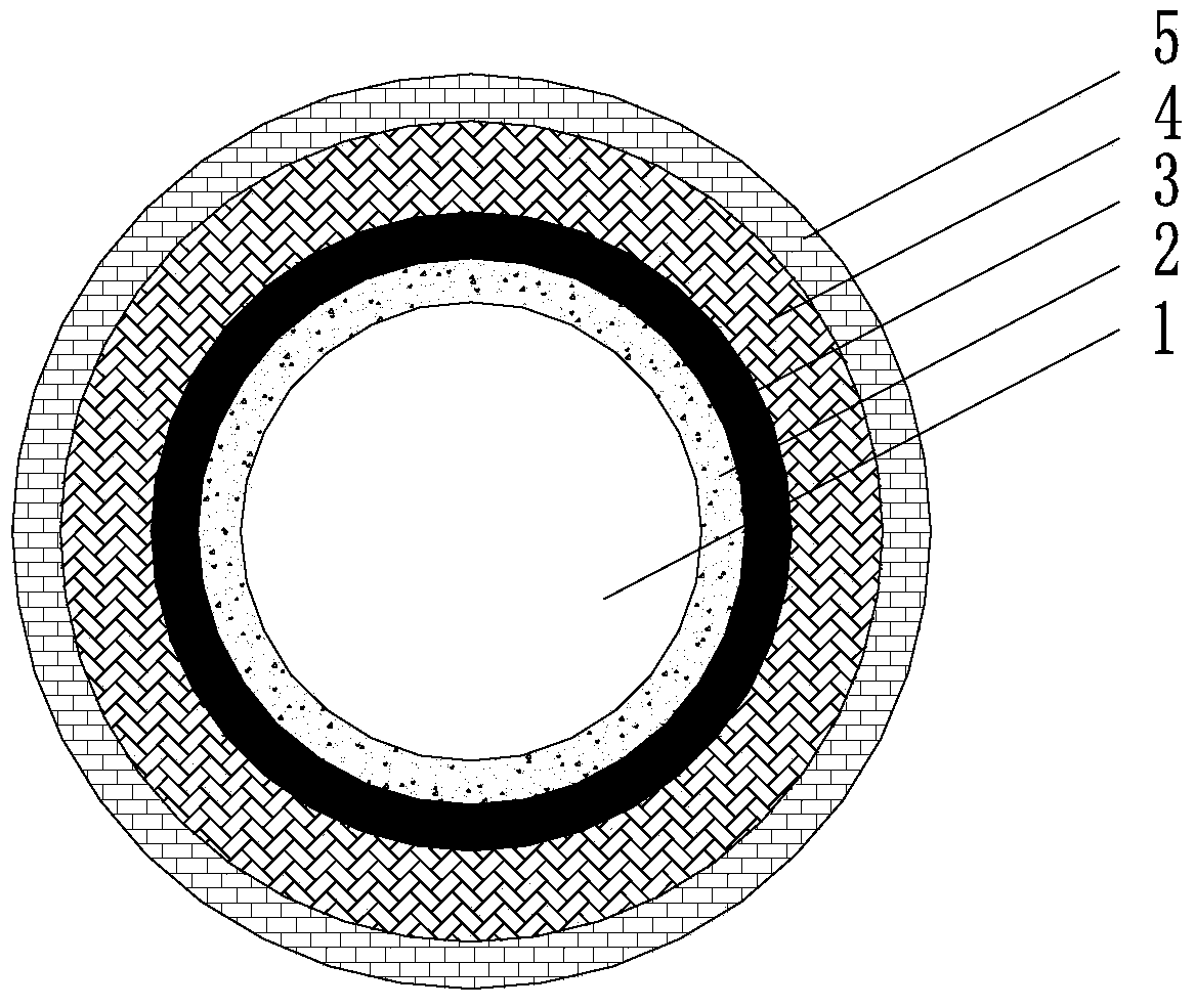
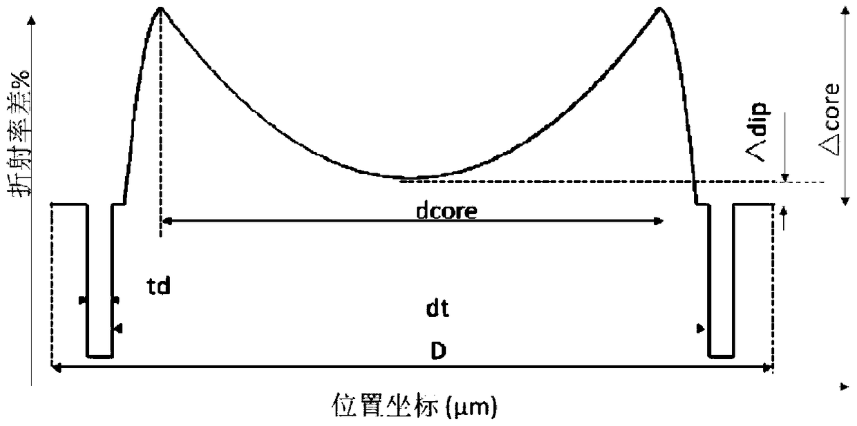
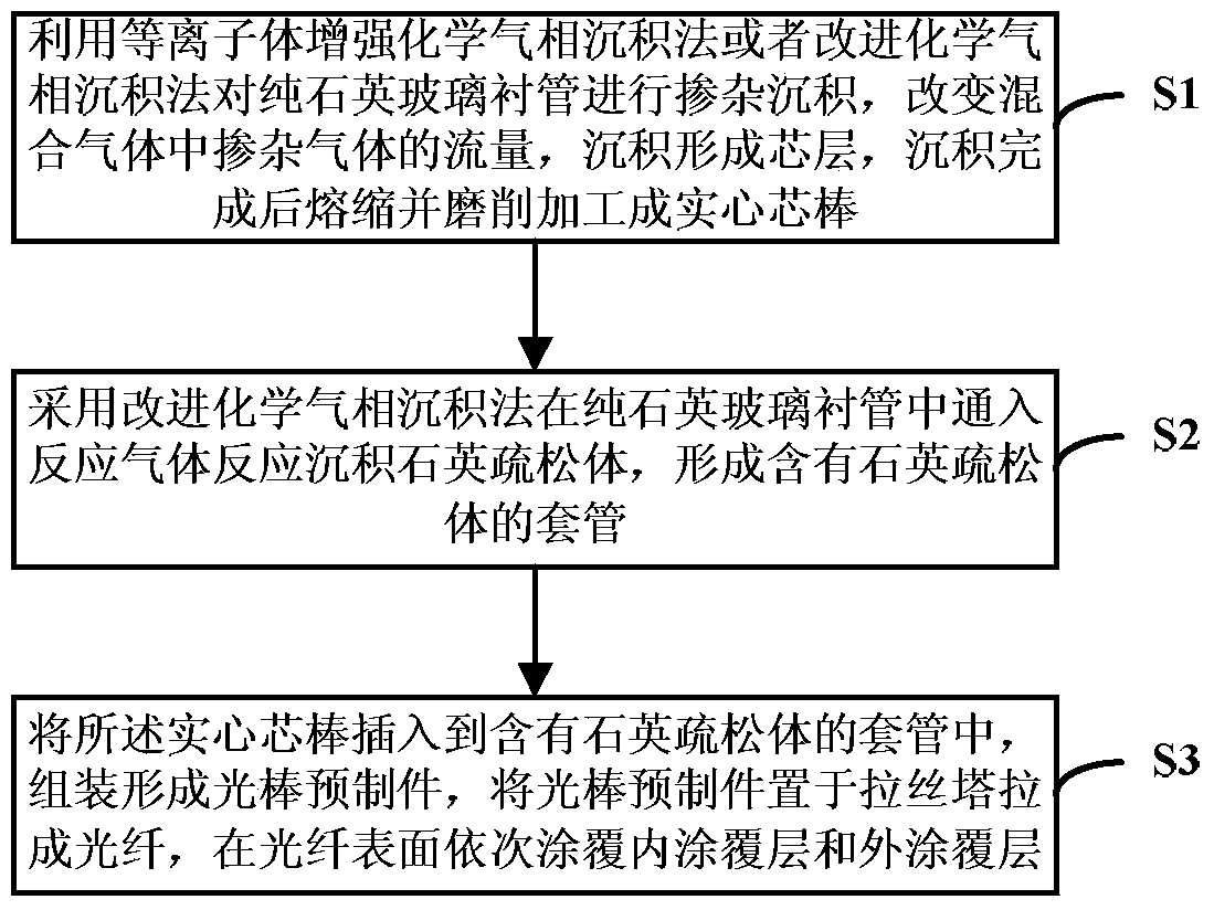

Image

  • Dispersion fiber for high-power transmission with quartz cladding and manufacturing method thereof
  • Dispersion fiber for high-power transmission with quartz cladding and manufacturing method thereof
  • Dispersion fiber for high-power transmission with quartz cladding and manufacturing method thereof

Examples


Embodiment Construction

[0025] In order to facilitate the understanding of the present invention, at first the professional terms involved in the present invention are collectively defined as follows:

[0026] Quartz Liner: A tubular substrate tube whose inner wall bears a glassy oxide deposit of plasma-enhanced chemical vapor deposition (PCVD) chemical reaction.

[0027] Sleeve: A quartz glass tube that meets certain geometrical indicators and doping requirements.

[0028] Core layer: It is located in the central part of the cross-section of the optical fiber and is the main light-guiding area of ​​the optical fiber.

[0029] Light-scattering first silica cladding: the ring-shaped region next to the core in the cross-section of the fiber.

[0030] Second Silica Cladding: The annular region in the fiber cross-section immediately adjacent to the silica cladding where light is scattered.

[0031] Relative refractive index difference:

[0032] Numerical aperture: NA=n 0 ×(2×Δ) 1 / 2 ;

[0033] Amo...


PUM

PropertyMeasurementUnit
diameteraaaaaaaaaa
diameteraaaaaaaaaa
diameteraaaaaaaaaa

Abstract

A quartz cladding large-power-transmission dispersion optical fiber and a manufacturing method thereof relate to the technical field of optical communication and related sensing devices. The dispersion optical fiber is composed of a core layer, a first quartz cladding and a second quartz cladding which are successively arranged from inside to outside. The core layer is doped with Ge element; the refractivity of the core layer changes in a gradual manner; and furthermore distribution power exponent is 1.5-3.3. The first quartz cladding contains bubbles and has a light scattering function. The refractivity of the second quartz cladding is higher than that of the first quartz cladding. The quartz cladding large-power-transmission dispersion optical fiber and the manufacturing method have advantages of enduring relatively high power and relatively high temperature, improving stability and reliability of the optical fiber, and effectively settling a color change problem of the optical fiber in illumination.

Description

technical field [0001] The invention relates to the technical field of optical communication and related sensor devices, in particular to a quartz-clad high-power transmission dispersion optical fiber and a manufacturing method thereof. Background technique [0002] Dispersion optical fiber, also known as linear optical fiber, side emitting optical fiber or whole body emitting optical fiber. When the incident light enters from the end face of the diffuse fiber, it can be emitted through the side surface of the entire fiber, thereby forming a whole-body luminescent fiber. Because it has such a unique luminous effect, it is often used in important scientific and technological fields such as medicine and environmental protection. [0003] Dispersion fiber generally consists of two parts: a fiber core with a high refractive index and an optical scattering cladding with a low refractive index. Generally, some dispersants are evenly mixed in the optical scattering cladding to de...

Claims


Application Information

Patent Timeline
Patent Type & Authority Patents(China)
IPC IPC(8): G02B6/036C03B37/012C03B37/025
Inventor 莫琦张涛陈如山刘志坚罗文勇柯一礼杜城但融雷琼严垒
Owner WUHAN POST & TELECOMM RES INST CO LTD
Learn More