High-power continuous fiber laser-based hot-drawing, molding and welding apparatus for spiral fin coil

A fiber laser and spiral finned tube technology, which is applied in the production field of spiral finned tubes, can solve the problems of low bonding strength, low thermal conversion efficiency, low precision of forming molds, etc. The effect of easy stretch forming

Active Publication Date: 2016-10-26
DONGGUAN AOXIN LASER WELDING EQUIP
View PDF10 Cites 5 Cited by
  • Summary
  • Abstract
  • Description
  • Claims
  • Application Information

AI Technical Summary

Problems solved by technology

Products made by this process have low bonding strength, no corrosion resistance, and low heat conversion efficiency
[0009] Chinese patent CN201410467460.5 discloses a CNC spiral fin tube laser welding forming equipment and its welding forming method. This method combines laser forming technology without changing the metallographic structure of the metal, and greatly improves the bonding effect between the fin and the steel pipe. , the strength is good, the product quality is good, but the cold forming process used in the process of forming the spiral fins on the steel strip, the stretchability (ductility) of the steel strip is not good, and it is easy to break. At the same time, when the steel pipe is in During the rotation process, due to the deviation in the size of the steel pipe, the coaxial rotation cannot always be maintained. In addition, during the welding process, a large amount of slag is difficult to effectively drain away. The accumulated slag reduces the precision of the forming mold and the anti-oxidation of the weld bead The performance is not good; at the same time, the straight-line walking trolley is driven by the motor belt, and the precision is low

Method used


Image

  • High-power continuous fiber laser-based hot-drawing, molding and welding apparatus for spiral fin coil
  • High-power continuous fiber laser-based hot-drawing, molding and welding apparatus for spiral fin coil
  • High-power continuous fiber laser-based hot-drawing, molding and welding apparatus for spiral fin coil

Examples


Embodiment Construction

[0031] The preferred embodiments of the present invention are given below in conjunction with the accompanying drawings to describe the technical solution of the present invention in detail.

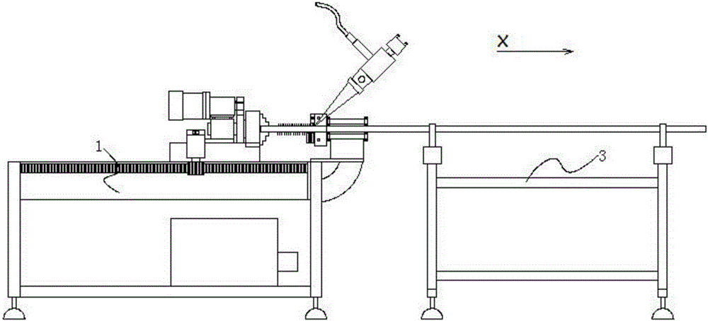
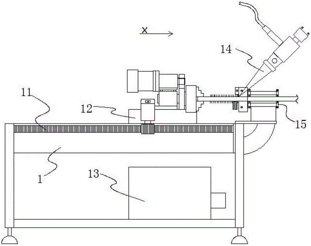
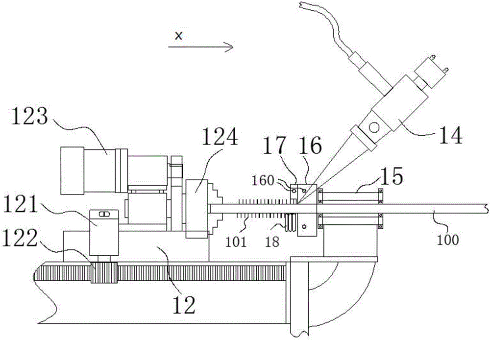
[0032] see Figure 1 to Figure 8 , an embodiment of a high-power continuous fiber laser spiral finned tube heat-drawing welding equipment, including a main frame 1, a pair of linear racks 11 are horizontally arranged on the main frame 1 along the X-axis direction, and the main shaft seat 12 is movably arranged on the main frame 1 and is located between a pair of linear racks 11, and a pair of traveling motors 121 are arranged vertically on the main shaft base 12, and a pair of traveling motors 121 are transmission-connected to the pair of linear racks. 11 engaged with a pair of gears 122, thereby driving the main shaft seat 12 to walk on the main frame 1, and then dragging the steel pipe 100 to move in the X-axis direction; the chuck rotating motor 123 is fixed on the main shaft seat 12,...


PUM


Abstract

The invention provides a high-power continuous fiber laser-based hot-drawing, molding and welding apparatus for a spiral fin coil. The apparatus comprises a main machine stand; a pair of linear tooth bars are fixedly mounted on the main machine stand; a spindle seat is arranged between the pair of linear tooth bars and is provided with a rotating chuck; the chuck rotates under the driving of a chuck rotation motor arranged on the spindle seat; the side, opposite to the chuck, of the main machine stand is provided with a double-cantilever mold base; a molding mold is adhered on one side surface of the double-cantilever mold base; a high-power continuous fiber laser is arranged above the double-cantilever mold base; a to-be-welded steel belt is fed along a Y-axis direction, passes through a guide pulley, an intelligent ultrahigh-frequency eddy-current heating machine and a constant-temperature oil tank which are arranged at one side of the double-cantilever mold base, and then extends to a place located between the molding mold and the double-cantilever mold base; and laser beams emitted by the fiber laser irradiate the extruding joint of a steel pipe and the steel belt for welding, so spiral fins are formed on the surface of the steel pipe. The invention has the beneficial effects that the integral precision and efficiency of the apparatus are greatly improved, and the molded spiral fin coil has greatly improved quality.

Description

technical field [0001] The invention relates to the technical field of spiral finned tube production, in particular to a high-power continuous fiber laser spiral finned tube heat-drawing welding equipment. Background technique [0002] Spiral finned tubes are used as heat exchanging elements, and they work under high temperature flue gas conditions for a long time. Performance. Such as anti-corrosion performance, wear resistance, low contact thermal resistance, high stability and anti-dusting ability, etc. [0003] There are several traditional production methods for spiral finned tubes. [0004] 1. Set of fins: The process of set fins is to pre-process a batch of individual fins, and then use manual or mechanical methods to set the fins on the outer surface of the tube by interference fit according to a certain fin distance. The coordination effect is poor, and the heat conversion efficiency is low. [0005] 2. Inlaid spiral fin: The inlaid spiral fin tube is to process...

Claims


Application Information

Patent Timeline
Patent Type & Authority Applications(China)
IPC IPC(8): B21C37/26
CPCB21C37/26
Inventor 王传礼
Owner DONGGUAN AOXIN LASER WELDING EQUIP
Why Eureka
Try Eureka