
Shunting type multi-pipe pulse detonation combustion chamber

A technology of pulse detonation and combustion chamber, applied in the direction of combustion chamber, continuous combustion chamber, combustion method, etc., can solve the problems of turbine blade erosion, turbine impact, etc., to reduce impact and thermal erosion, and reduce pulsation , increase the effect of mixing time and space

Active Publication Date: 2016-10-26
NORTHWESTERN POLYTECHNICAL UNIV
View PDF5 Cites 20 Cited by
  • Summary
  • Abstract
  • Description
  • Claims
  • Application Information

AI Technical Summary

Problems solved by technology

[0004] The technical problem to be solved by the present invention is: in order to solve the problems such as the burning of the turbine blades by the transient high temperature and the impact of the periodic air flow on the turbine during the matching work between the pulse detonation combustion chamber and the turbine, the present invention provides a The split-flow multi-tube pulse detonation combustor can adjust the exhaust temperature of the detonation chamber and slow down the impact of the exhaust gas on the turbine through the reasonable distribution of the intake and exhaust of multiple pairs of detonation chambers.

Method used


Image

  • Shunting type multi-pipe pulse detonation combustion chamber
  • Shunting type multi-pipe pulse detonation combustion chamber
  • Shunting type multi-pipe pulse detonation combustion chamber

Examples


Embodiment approach 1

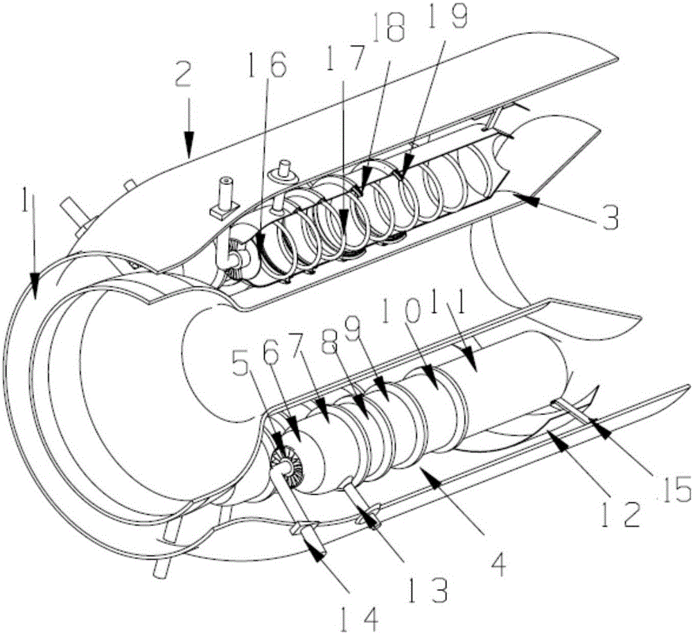
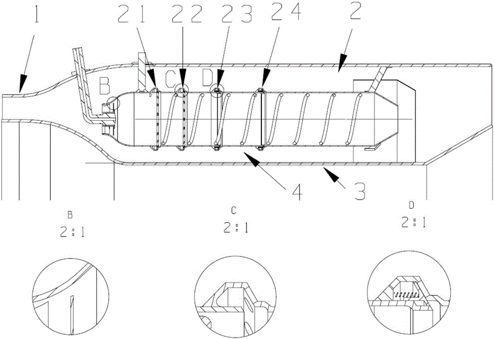
[0021] A split multi-tube pulse detonation combustion chamber described in this embodiment is as follows: figure 1 As shown, it includes a pre-diffuser 1 of the combustion chamber, a casing 2 outside the combustion chamber, a casing 3 inside the combustion chamber, a fuel nozzle 14 , a spark plug, a circular detonation tube 4 and a guide ring 12 . The six detonation tubes are distributed in a ring, and the central angle of the central axis of the two adjacent detonation tubes is 60°. The detonation tube 4 is fixed outside the combustion chamber through the fuel supply seat, the ignition mounting seat 13 and the guide ring fin 15 on the receiver. Outside the combustion chamber, the inner and outer casings 2 and 3 are connected by the turbine guide vane and the compressor diffuser vane. The guide ring 12 is a ring of flakes to stabilize the detonation gas and reduce the mixing loss. The ignition installation The seat is used to install the spark plug mouth. The detonation tube...

Embodiment approach 2

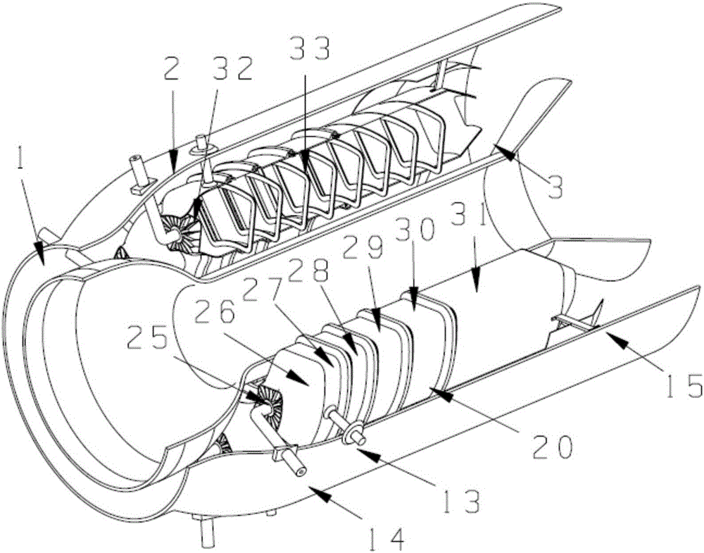
[0024] As a second embodiment of the present invention, see figure 2 , the circular detonation tube 4 is replaced by a fan-shaped detonation tube 20 . The corresponding central angle of the fan-shaped detonation tube 20 is 45°, the radius of the inner arc is 1.25 times the radius of the casing 3 inside the combustion chamber, and the radius of the outer arc is 7 / 8 of the casing 2 outside the combustion chamber. The ignition seat is on the outer arc of the ignition section. Sector-shaped detonation tube 20 is made up of head sector-shaped air intake section 26, sector-shaped ignition section 27, sector-shaped detonation section a28, sector-shaped detonation section b29, sector-shaped detonation section c30, and sector-shaped detonation section d31. The valve plate 32 used on the fan-shaped detonation tube 20 is also fan-shaped, and the detonation enhancement device is changed to a fan-shaped obstacle 33, and the working mode of the fan-shaped detonation tube is the same as th...


PUM


Abstract

The invention provides a shunting type multi-pipe pulse detonation combustion chamber. After airflow passes through a front diffuser of the combustion chamber, part of the airflow flows into detonation pipes from the head portions of the detonation pipes, and the other part of the airflow flows through the outside of the detonation pipes; a valve block is arranged on the head portion of each detonation pipe, and four deflation rings are arranged on each detonation pipe; in a filling state, the valve blocks on the heat portions are opened so that air can enter the detonation pipes, the first two deflation rings on each detonation pipe are used for auxiliary air intake to increase the filling speed, and one-way valves are installed in the last two deflation rings on each detonation pipe; and the valves are closed in the filling stage. In the spreading and combustion product discharging stage formed by detonation waves, the gas pressure in the detonation pipes is higher than the pressure outside the detonation pipes, the air inlet valve blocks on the head portions are closed, the exhaust valves are opened, part of high-pressure high-temperature gas is exhausted from the deflation rings to be mixed with the airflow outside the detonation pipes, and the other part of the high-pressure high-temperature gas is exhausted from the tail portions of the detonation pipes and exhausted into a turbine after being mixed in a combustion chamber case. Through the two mixing processes, the effects of adjusting the exhaust temperature of the detonation chamber and reducing the impact of exhaust gas to the turbine are achieved.

Description

technical field [0001] The invention belongs to the technical field of engines, in particular to a split-flow multi-tube pulse detonation combustion chamber. Background technique [0002] Pulse detonation engine (PDC) is a new concept engine that uses high-temperature and high-pressure gas generated by periodic detonation waves to generate thrust. This engine has been favored by researchers at home and abroad because of its high cycle thermal efficiency and simple structure. widespread attention. According to whether it has its own oxidant, the pulse detonation engine can work in two modes: air-breathing and rocket. The air-breathing pulse detonation engine is divided into basic pulse detonation engine, pulse detonation turbine engine and combined Pulse detonation engine. The basic pulse detonation engine is mainly composed of an intake port, a detonation combustion chamber and a tail nozzle. The high-temperature, high-speed detonation gas is directly discharged from the de...

Claims


Application Information

Patent Timeline
Patent Type & Authority Applications(China)
IPC IPC(8): F23R3/00
CPCF23R3/00
Inventor 郑龙席王凌羿
Owner NORTHWESTERN POLYTECHNICAL UNIV
Learn More