Eureka AIR delivers breakthrough ideas for toughest innovation challenges, trusted by R&D personnel around the world.

Detection Raman laser radar light path system

An optical path system and Raman laser technology, applied in the field of detecting Raman lidar optical path systems, can solve the problems of heavy workload of inspection personnel, high inspection cost, waste of resources, etc. The effect of workload

Inactive Publication Date: 2016-10-26
BEIFANG UNIV OF NATITIES
View PDF10 Cites 6 Cited by
  • Summary
  • Abstract
  • Description
  • Claims
  • Application Information

AI Technical Summary

Problems solved by technology

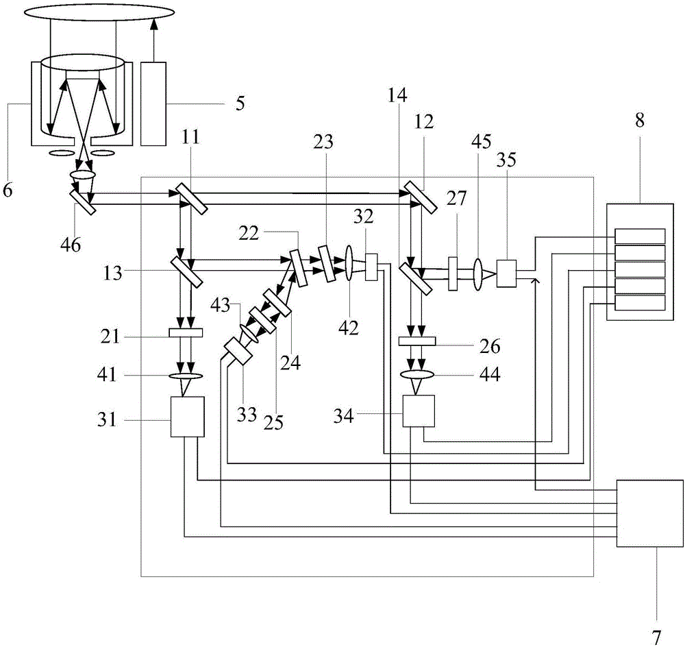
[0004] The purpose of the present invention is to provide a detection Raman lidar optical path system to solve the problem of single detection of atmospheric temperature, water vapor, nitrogen and aerosol in the prior art, which needs to use different equipment for detection, thereby making the detection cost high. Waste of resources, time-consuming, heavy workload of testing personnel, and the equipment used is bulky, complex in structure, cumbersome in testing systems, etc.

Method used


Image

  • Detection Raman laser radar light path system
  • Detection Raman laser radar light path system

Examples


Embodiment Construction

[0033] The technical solutions of the present invention will be clearly and completely described below in conjunction with the accompanying drawings. Apparently, the described embodiments are some of the embodiments of the present invention, but not all of them. Based on the embodiments of the present invention, all other embodiments obtained by persons of ordinary skill in the art without making creative efforts belong to the protection scope of the present invention.

[0034]In the description of the present invention, it should be noted that the terms "center", "upper", "lower", "left", "right", "vertical", "horizontal", "inner", "outer" etc. The indicated orientation or positional relationship is based on the orientation or positional relationship shown in the drawings, and is only for the convenience of describing the present invention and simplifying the description, rather than indicating or implying that the referred device or element must have a specific orientation, o...


PUM

PropertyMeasurementUnit
Center wavelengthaaaaaaaaaa

Abstract

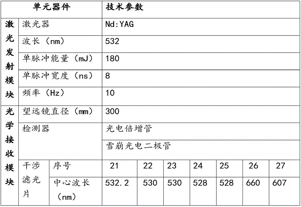
The invention provides a detection Raman laser radar light path system and relates to the laser atmosphere remote sensing technology field. The detection Raman laser radar light path system comprises a laser emission module, an optical receiving module and a data acquisition module. Second harmonic generation 532nm pulse laser emitted by the laser emission module to atmosphere is interacted with atmosphere particles so as to generate a scattered light signal. The scattered light signal carries out retroreflection and is received by a telescopic system of the optical receiving module. Received light is successively divided into five layers and simultaneously light splitting processing is performed, and then the light is processed by the data acquisition module. In the prior art, for single detection of an atmospheric temperature, moisture, nitrogen and aerosol, different equipment needs to be used to carry out detection so that detection cost is high; resources are wasted; time is wasted too; a detection personnel workload is large; the size of the equipment is large too; the structure is complex; and a detection system is tedious and so on. By using the detection Raman laser radar light path system provided in the invention, the above problems are solved.

Description

technical field [0001] The invention relates to the technical field of laser atmospheric remote sensing, in particular to an optical path system for detecting Raman lidar. Background technique [0002] Lidar is an advanced detection technology combining laser technology and modern photoelectric detection technology, which uses lasers as the emission light source and uses photoelectric detection technology as an active remote sensing device. Because lidar has the advantages of high detection sensitivity and high spatial resolution, it has become an effective method for high-precision remote sensing detection of the atmosphere, ocean and land. Lidar can use the interaction between laser and air molecules and aerosol particles existing in the atmosphere to realize the active remote sensing detection of atmospheric optical and physical characteristics, as well as atmospheric meteorological parameters. [0003] In the current market, lidar is mainly aimed at the single detection...

Claims


Application Information

Patent Timeline
IPC IPC(8): G01S7/481G01S17/88G01S17/95
CPCG01S7/481G01S7/4812G01S17/88G01S17/95Y02A90/10
Inventor 毛建东刘凯殷利庆孙颖王朝飞秦学珍
Owner BEIFANG UNIV OF NATITIES
Why Eureka
Eureka Blog
Learn More