
Rotational flow type spiral sedimentation device with automatic control system sludge discharge function

A technology of automatic control system and sedimentation device, which is applied in the feeding/discharging device of sedimentation tank, sedimentation separation, flocculation/sedimentation water/sewage treatment, etc. It is difficult to achieve water treatment effect, difficult to have solid-liquid separation efficiency and other problems, to achieve the effect of improving solid-liquid separation efficiency, flexible operation flexibility and stability, and increasing hydraulic retention time

Active Publication Date: 2016-11-09
CHINA RAILWAY DESIGN GRP CO LTD
View PDF5 Cites 7 Cited by
  • Summary
  • Abstract
  • Description
  • Claims
  • Application Information

AI Technical Summary

Problems solved by technology

According to the classic sedimentation theory, considering many factors in the particle sedimentation process, the sedimentation tank can achieve the purpose of solid-liquid separation through gravity, but due to the limitation of form and structure, it is difficult to realize the sedimentation process of short distance and long stroke; at the same time, considering Due to land occupation and other reasons, it is impossible to provide a long settling time for solid-liquid separation, and it is difficult to have high-efficiency solid-liquid separation efficiency, which is far from the ideal settling effect. Especially for water treatment projects that need to increase flocculation, there is no high-efficiency settling process, it is difficult to achieve good water treatment effect

Method used


Image

  • Rotational flow type spiral sedimentation device with automatic control system sludge discharge function
  • Rotational flow type spiral sedimentation device with automatic control system sludge discharge function

Examples


Embodiment Construction

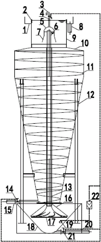
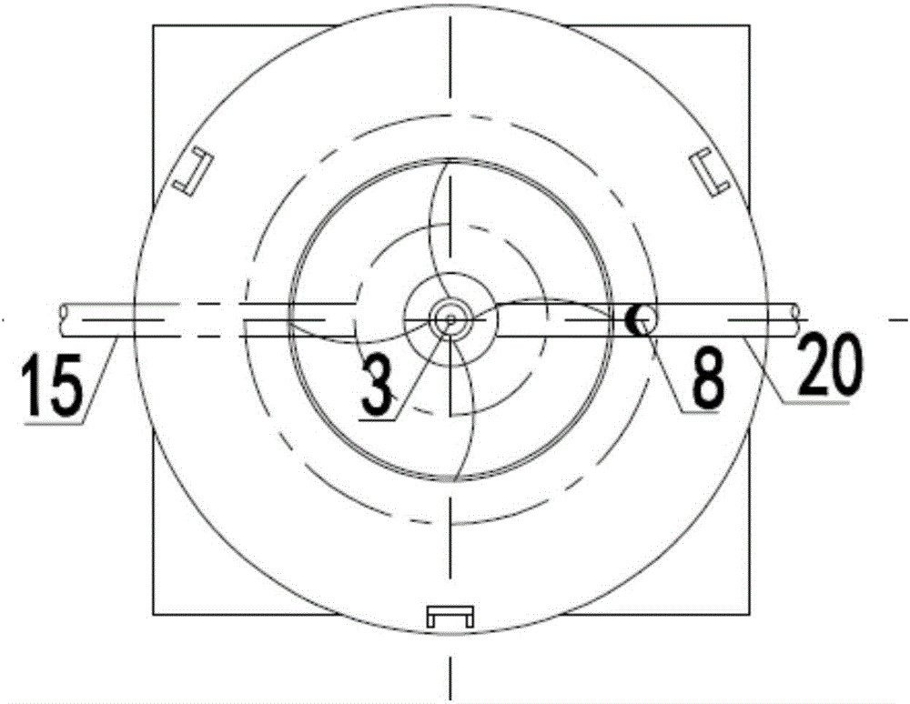
[0034] The technical solution of the present invention will be further described in conjunction with the accompanying drawings. figure 1 and figure 2 The basic structure of the present invention is shown.

[0035] As shown in the drawings, the raw water to be separated from solid and liquid enters the inverted cone 12 of the cyclone sedimentation device through the water inlet pipe 15, the flow rate is controlled by the water inlet pipe control valve 14, and the fluid spirals upward through the fixed guide spiral piece 11. At this time The solid particles in the fluid are reduced by gravity and impact, and fall on 11, most of them will move in the opposite direction with the fluid under the action of gravity, and slowly flow into the lower cone 18 of the mud deposit, and the remaining small part will Reach a speed balance with the fluid, and temporarily stay on 11; the fluid continuously rises through 11 and enters the cylinder 10 of the cyclone sedimentation device. At this...


PUM


Abstract

The invention discloses a rotational flow type spiral sedimentation device with an automatic control system sludge discharge function. The rotational flow type spiral sedimentation device comprises a siphon device at the top, a rotational flow sedimentation device in the middle and an automatic control sludge discharge device at the bottom; a siphon water storage tank of the siphon device is directly connected with a cylinder of the rotational flow sedimentation device, a divergent semicircular siphon cover is located in the center of the siphon water storage tank, and an adjustable weir plate is installed on a water outlet groove; a sludge interface instrument continuously monitors change of sludge level height in a sludge storing lower cone, and on-off of a delay electromagnetic control valve, a water inlet pipe control valve and a sludge discharge control valve is controlled through a signal feedback controller to achieve automatic siphon sludge discharge. According to the shallow pool theory, efficient solid-liquid separation in a rotational flow state is achieved, and the purposes of auxiliary solid-liquid separation and automatic sludge discharge are achieved by using the siphon principle. The device is simple in structure and saves land by means of vertical arrangement, signal feedback linkage control exists in the operation process, operation management is convenient, full automatic operation can be achieved, the failure rate is low, the concept of saving energy and reducing consumption in water treatment is met, and the spiral sedimentation device is suitable for various water treatment occasions.

Description

technical field [0001] The invention relates to water treatment sedimentation technology, in particular to a cyclone spiral sedimentation device for water treatment. Background technique [0002] Water treatment particle physical precipitation engineering is one of the most basic and most commonly used methods in water treatment. It is a process of separating solid and liquid by gravity according to the density difference between suspended particles in water and water itself. This method is a commonly used physical treatment technology and an essential process in water treatment technology. The sedimentation structures established by this technology are called grit chambers or sedimentation tanks in the water treatment process. Sedimentation tanks are widely used in water treatment, and there are many types. According to the direction of water flow in the tank, they can be divided into three types: advection type, vertical flow type and radial flow type. According to the c...

Claims


Application Information

Patent Timeline
Patent Type & Authority Applications(China)
IPC IPC(8): B01D21/26B01D21/24B01D21/34C02F1/52
CPCB01D21/245B01D21/267B01D21/34C02F1/52
Inventor 张义龙翟计红马敏杰车跃龙魏举旺周继超裴露
Owner CHINA RAILWAY DESIGN GRP CO LTD
Learn More