
A welding method for fuel oil pipe

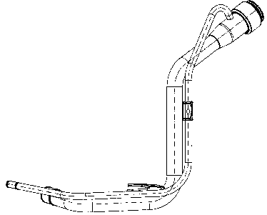
A welding method and technology for refueling pipes, applied in welding equipment, arc welding equipment, metal processing equipment, etc., can solve the problems of easy aging, low service life, large heating area, etc., and achieve strong anti-corrosion performance, long service life, and reliability. good effect

Inactive Publication Date: 2018-07-03
张利
View PDF6 Cites 0 Cited by
  • Summary
  • Abstract
  • Description
  • Claims
  • Application Information

AI Technical Summary

Problems solved by technology

[0002] At present, gas welding is mostly used in the welding process of fuel pipes. The welding temperature is high and the heating area is large, which makes the surface of the galvanized layer oxidize rapidly and destroys its corrosion resistance.
At the same time, the installation method of the spiral sleeve: the spiral sleeve is installed by inlaying the inner sealant. The disadvantages are poor reliability, easy aging, low service life, chemical reaction to the oil body itself, and poor sealing performance.

Method used


Image

  • A welding method for fuel oil pipe

Examples


Embodiment 1

[0020] A welding method for fueling pipes. The filling pipes, exhaust pipes, spiral sleeves, and brackets are clamped into the welding mold at one time and pressed firmly with mechanical hands. Argon arc welding machines and copper alloy welding rods (alloy copper welding rods are used The SCu6560 copper alloy welding rod produced by Beijing Yida Kuntai Technology Co., Ltd. is used to fix the parts by spot welding, take them out of the mold, and then perform assembly welding. When welding the filling pipe, exhaust pipe and bracket, it is argon arc welding. The current used is: 98A, and the welding spiral sleeve is argon arc welding rotary welding. The used current is: 110A; the linear speed is: 15-16mm / s, and the welding process is formed at one time. After the welding is completed, check the air tightness to check whether there are air holes. Use the air compressor to immerse the filling pipe in the water tank to see if there are bubbles. Set the pressure at 0.02MPa for 30s to...

Embodiment 2

[0022] A welding method for fueling pipes. The filling pipes, exhaust pipes, spiral sleeves, and brackets are clamped into the welding mold at one time and pressed firmly with mechanical hands. Argon arc welding machines and copper alloy welding rods (alloy copper welding rods are used The SCu6560 copper alloy welding rod produced by Beijing Yida Kuntai Technology Co., Ltd. is used to fix the parts by spot welding, take them out of the mold, and then perform assembly welding. When welding the filling pipe, exhaust pipe and bracket, it is argon arc welding. The current used is: 98A, and the welding spiral sleeve is argon arc welding rotary welding, the used current is: 110A; the linear speed is: 15mm / s, and the welding process is formed at one time. After the welding is completed, check the air tightness to check whether there are air holes. Use the air compressor to immerse the filling pipe in the water tank to see if there are bubbles. Set the pressure at 0.02MPa for 30s to se...


PUM


Abstract

The invention belongs to the technical field of automobile part processing and particularly relates to a welding method for an oil filling pipe. The welding method comprises the steps that a filling pipe body, an exhaust pipe body, a spiral sleeve and a bracket are clamped into a welding mold at a time and pressed firmly through a mechanical hand, and all the parts are subjected to spot welding and fixing through an argon arc welding machine and copper alloy welding rods, taken out from the mold and then subjected to assembly welding; after welding is completed, gas tightness detection is conducted, then comprehensive test instrument detection is conducted according to the drawing size, and deformation adjustment needs to be conducted if the oil filling pipe is unqualified; surface anti-corrosion treatment is conducted; and high-temperature curing is conducted. According to the welding method for the oil filling pipe, argon arc welding spin welding and the copper welding rods are adopted, thus, the reliability is good, aging is not prone to happening, the structure of an original corrosion-resistant layer is ensured, and the service life is long; low-temperature welding is conducted, the effect that welding and fixing are stable is achieved, and meanwhile, a galvanized layer is not destroyed; and the optimum current and the optimum rotation speed are set, so that the anti-corrosion performance of the welded oil filling pipe is high, and no sand hole occurs.

Description

technical field [0001] The invention belongs to the technical field of auto parts processing, and in particular relates to a welding method for an oil filling pipe. Background technique [0002] At present, gas welding is mostly used in the welding process of fuel pipes. The welding temperature is high and the heating area is large, which makes the surface of the galvanized layer oxidize rapidly and destroys its corrosion resistance. At the same time, the installation method of the spiral sleeve: the spiral sleeve is installed by inlaying the inner sealant. The disadvantages are poor reliability, easy aging, low service life, chemical reaction to the oil body itself, and poor sealing performance. Contents of the invention [0003] The purpose of the present invention is to provide a processing method for filling pipes, in order to achieve the above purpose: the present invention provides the following technical solutions: [0004] A welding method for a refueling pipe, wh...

Claims


Application Information

Patent Timeline
Patent Type & Authority Patents(China)
IPC IPC(8): B23K9/16
CPCB23K9/0052B23K9/007B23K9/16
Inventor 张利
Owner 张利
Learn More