Extrusion mechanism of intelligent hydraulic extruder for manufacturing environment-friendly bio-fuel
A technology of biofuel and extrusion mechanism, which is applied in the direction of material forming presses, presses, manufacturing tools, etc., can solve the problems of low environmental pollution, insufficient extrusion effect, and insufficient efficiency, and achieve high work efficiency and structure Simple, good extrusion effect
- Summary
- Abstract
- Description
- Claims
- Application Information
AI Technical Summary
Problems solved by technology
Method used
Image

Examples
Embodiment 1
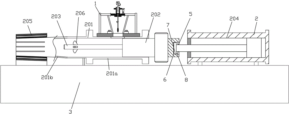
[0040] Embodiment 1: as figure 1 , 2 As shown, the extrusion machine includes an extrusion frame 3, a PLC control device, a feeding mechanism 1 and an extrusion mechanism 2; the extrusion mechanism of an intelligent hydraulic extrusion machine for manufacturing environmentally friendly biofuels, and the extrusion mechanism 2 includes The extruding tube 201 communicated with the feeding mechanism 1, the extruding piston 202 inserted in the extruding tube 201 with clearance fit, the extruding rod 203 fixed on one end of the extruding piston 202 and the extruding rod 203 for driving The extrusion piston 202 reciprocates in the extrusion cylinder 204 in the extrusion tube 201, the extrusion tube 201 includes a straight pipe section 201a and a tapered extrusion section 201b; a PLC control device and an extrusion piston home position sensor , The end sensor of the extrusion piston is connected. When the extrusion piston is extruding, when it reaches the end point, the end sensor of...
Embodiment 2
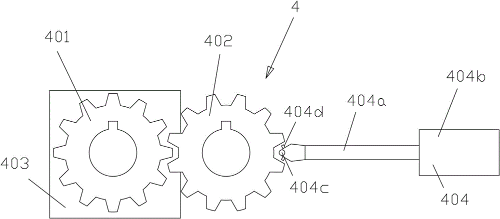
[0045] Embodiment 2, see attached Figure 4 , 5 , and Example 1 is different in that, in this embodiment, the feed mechanism includes a feed hopper 101 with a feed inlet and a feed outlet, a mounting frame 102, a first reduction motor 103, and the first reduction motor The cam 104 fixedly connected to the output shaft of the motor 103, the rotary drive part 106 installed on the mounting frame 102, and the cam 104 that is installed on the mounting frame 102 is driven to move up and down and driven by the rotary drive part 106. Rotating feed part 105; the feed part 105 includes a rotating shaft 10501 provided on the mounting frame 102, an axial cavity 10502 provided on the rotating shaft 10501, and an axial cavity 10502 provided in the axial cavity 10502 The spline hole 10503, the spline shaft 10505 matched with the spline hole 10504, the lower feeding rod 10506 fixed on the spline shaft 10505, the upper ejector rod 10507 fixed on the spline shaft 10505 , the elastic reset mem...
Embodiment 3
[0050] Embodiment 3, see attached Image 6 , in this embodiment, the difference from Example 1 is that the lower end of the lower feeding rod 10506 is not provided with a rolling steel ball 111, but is provided with a stirring tube 115, and the lower end of the stirring tube 115 is provided with a tapered inner Holes, the tapered inner hole is provided with a supporting round table 116, the supporting round table can move in the tapered hole, the connecting rod 117 inserted in the stirring tube 115 is fixed on the supporting round table 116, the connecting rod The return spring 118 is set on the 117, and the lower end of the stirring tube 115 is evenly distributed with a plurality of open grooves 119, and an expansion rib 120 is formed between two adjacent open grooves, and the width of the open groove is 1-2mm; further, the lower inclined plate The upper end of 108 is bent downward and inward to form an upper bent plate (not shown in the figure).
PUM
 Abstract
Description
Claims
Application Information
 - R&D
- Intellectual Property
- Life Sciences
- Materials
- Tech Scout
- Unparalleled Data Quality
- Higher Quality Content
- 60% Fewer Hallucinations
Browse by: Latest US Patents, China's latest patents, Technical Efficacy Thesaurus, Application Domain, Technology Topic, Popular Technical Reports.
© 2025 PatSnap. All rights reserved.Legal|Privacy policy|Modern Slavery Act Transparency Statement|Sitemap|About US| Contact US: help@patsnap.com