Petroleum drilling waste mud reduction zero-release recycling system and method

A waste mud and oil drilling technology, applied in chemical instruments and methods, sludge treatment, water/sludge/sewage treatment, etc., can solve the problems of sustainable development of oilfields, vegetation and water pollution, transportation difficulties, etc., to achieve Reduce the cost of pollution control, reduce the cost of drilling operations, and reduce the effect of hidden dangers of pollution

Pending Publication Date: 2016-11-09
TIANJIN FANYINDETAI PETROLEUM ENVIRONMENTAL PROTECTION TECH DEV INC
View PDF6 Cites 3 Cited by
  • Summary
  • Abstract
  • Description
  • Claims
  • Application Information

AI Technical Summary

Problems solved by technology

[0002] Petroleum drilling waste mud is produced every moment during the drilling work of major oil fields in my country. Research shows that the drilling mud generally used in oil fields in my country is less oil-based mud, mainly water-based mud, whose chemical composition makes the mud appear strong alkali highly corrosive, difficult to transport, and oil d

Method used


Image

  • Petroleum drilling waste mud reduction zero-release recycling system and method
  • Petroleum drilling waste mud reduction zero-release recycling system and method

Examples


Embodiment 1

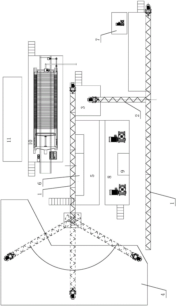
[0038] as attached figure 1 As shown, a waste oil drilling mud reduction and zero-emission reuse system includes a forward and reverse screw conveyor 1 arranged at the wellhead, and the forward and reverse screw conveyor 1 is connected to a vibrating screen 3 through a shaftless screw conveyor 2 , the vibrating screen 3 is connected to the waste material area 4 through the forward and reverse screw conveyor 1, the vibrating screen 3 is connected to the mud storage tank 5 through the pipeline, and the mud storage tank 5 is connected through the submerged slurry pump A horizontal centrifuge 6, the horizontal centrifuge 6 is connected to the waste material area 4 through the forward and reverse screw conveyor 1, and the waste material area 3 is connected by a conveyor belt to move the skid-mounted organic sewage The mud is reused in the rotary kiln.

[0039] In this embodiment, the mud storage tank 5 is connected with a mud buffer tank, the mud buffer tank is provided with a mix...

Embodiment 2

[0048] A reduction and zero-discharge reuse system for oil drilling waste mud, including a forward and reverse screw conveyor 1 arranged at the wellhead, the forward and reverse screw conveyor 1 is connected to a vibrating screen 3 through a shaftless screw conveyor 2, the The vibrating screen 3 is connected to the waste material area 4 through the forward and reverse screw conveyor 1, the vibrating screen 3 is connected to the mud storage tank 5 through the pipeline, and the mud storage tank 5 is connected to the horizontal centrifuge through the submerged slurry pump. The horizontal centrifuge 6 is connected to the waste material area 4 through the forward and reverse screw conveyor 1 .

[0049] The mud storage tank 5 is connected with a mud reaction tank 8, and the mud reaction tank 8 is connected with a dosing tank 9, and the mud reaction tank 8 is also connected with a plate and frame filter press 10 through a pipeline flocculation mechanism, and the plate and frame The f...

Embodiment 3

[0056] A method for reusing oil drilling waste mud, comprising the following steps:

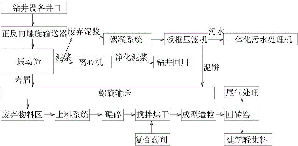
[0057] A. Drilling waste mud generated during oil drilling is received by positive and negative screw conveyors, and the mud is transported to the vibrating screen by the shaftless screw conveyor; when the mud viscosity is small and thick, it cannot be transported to the vibrating screen by the shaftless screw conveyor , The mud will enter the ground tank through the pipeline at the interface between the positive and negative screw conveyor and the shaftless screw conveyor. A mixer is installed in the ground tank, and the mud is pumped into the vibrating screen by the submerged slurry pump for subsequent processing.

[0058] B. After the vibrating screen screens out the large cuttings particles, they are transported to the waste material area by the positive and negative screw conveyors. The separated mud enters the mud storage tank, and is pumped into the horizontal centrifuge by the submerge...


PUM


Abstract

The invention relates to the technical field of petroleum drilling waste mud recycling treatment, in particular to a petroleum drilling waste mud reduction zero-release recycling system and method. The system comprises a forward and reverse spiral conveyor arranged at the mouth of a well of drilling equipment, the forward and reverse spiral conveyor is connected with a vibration sieve through a non-shaft spiral conveyor, the vibration sieve is connected with a waste material region through the forward and reverse spiral conveyor, the vibration sieve is connected with a mud storage tank through a pipeline, the mud storage tank is connected with a horizontal type centrifugal machine through a submersible slurry pump, the horizontal type centrifugal machine is connected with the waste material region through the forward and reverse spiral conveyor, the waste material region is connected with a movable prying type organic sludge recycling rotary kiln through a conveyor belt. According to the petroleum drilling waste mud reduction zero-release recycling system and method, mud non-grounding equipment is adopted, and waste mud reduction and recycling are achieved; in addition, waste mud and debris mud-water separation recycling can be achieved.

Description

technical field [0001] The invention relates to the technical field of recovery and treatment of waste oil drilling mud, in particular to a system and method for reducing waste oil drilling mud and reusing it with zero discharge. Background technique [0002] Petroleum drilling waste mud is produced every moment during the drilling work of major oilfields in my country. Studies have shown that the drilling mud generally used in oilfields in my country is less oil-based mud, mainly water-based mud. Its chemical composition makes the mud appear strong alkali highly corrosive, difficult to transport, and oil drilling waste mud contains harmful substances such as oil, organic matter and heavy metals. [0003] During the oil drilling process, the oil drilling waste mud directly falling into the ground will bring great pollution and damage to the soil, vegetation and water sources, and have a serious impact on the sustainable development of the oil field in the later stage. Conte...

Claims


Application Information

Patent Timeline
IPC IPC(8): C02F11/12C02F11/14
CPCC02F11/12C02F11/122C02F11/14C02F2303/06
Inventor 赵勇
Owner TIANJIN FANYINDETAI PETROLEUM ENVIRONMENTAL PROTECTION TECH DEV INC
Why Eureka
Try Eureka