Installation method for multi-cavity steel column shear wall composite structure building system

An installation method and technology of combined structure, applied in the processing of building materials, construction, building components, etc., can solve the problems of complex structure and poor performance.

Inactive Publication Date: 2016-11-09
潮峰钢构集团有限公司
View PDF6 Cites 7 Cited by
  • Summary
  • Abstract
  • Description
  • Claims
  • Application Information

AI Technical Summary

Problems solved by technology

This structure is relatively complex, and the performance is not good

Method used


Image

  • Installation method for multi-cavity steel column shear wall composite structure building system
  • Installation method for multi-cavity steel column shear wall composite structure building system
  • Installation method for multi-cavity steel column shear wall composite structure building system

Examples


Embodiment 1

[0110] Embodiment 1: An installation method of a multi-cavity steel column shear wall composite structure building system is characterized in that it is carried out in the following steps:

[0111] (1) Setting of foundation and supporting surface:

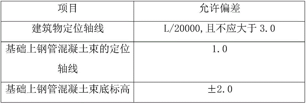
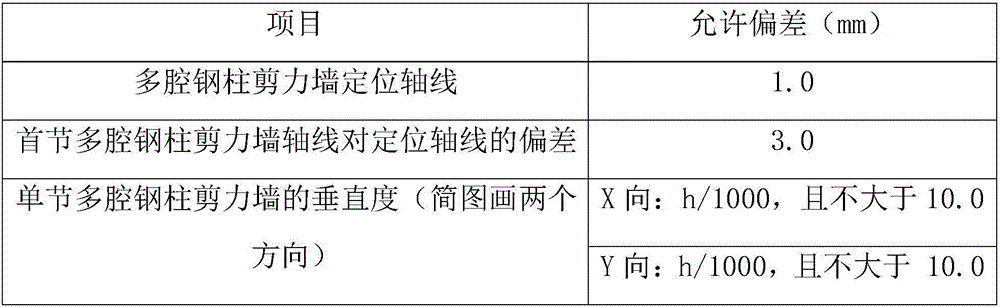
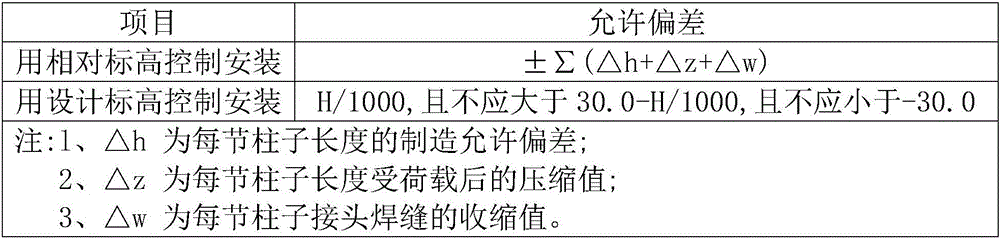
[0112] 1. The positioning axis of the building, the positioning axis and elevation of the multi-cavity steel column shear wall on the foundation shall meet the design requirements;

[0113] When there is no requirement in the design, it shall comply with the provisions in Table 1:

[0114] Inspection quantity: full inspection;

[0115] Inspection method: use theodolite, level, total station and steel ruler to measure;

[0116] Table 1 Allowable deviation of building positioning axis, positioning axis and elevation of the multi-cavity steel column shear wall on the foundation (mm)

[0117]

[0118]

[0119] 2. When the pre-embedded steel plate or support on the top surface of the foundation is used as the supporting surface...


PUM


Abstract

The invention relates to a shear wall composite structure, in particular to an installation method for a multi-cavity steel column shear wall composite structure building system. The installation method comprises the following steps of 1, base and supporting surface setting, 2, installing and correcting, 3, multi-cavity steel column shear wall internal concrete engineering, and 4, completing and acceptance of parts of construction of a steel structure. According to the shear wall composite structure installation method, the structure is compact, usable areas are increased, and the quality is ensured.

Description

technical field [0001] The invention relates to a shear wall composite structure, in particular to an installation method for a building system of a multi-cavity steel column shear wall composite structure. Background technique [0002] The multi-high-rise residential buildings in the prior art are relatively unreasonable, and H-shaped steel columns or box-shaped columns are mostly used. The structural system is a steel frame-core tube structure or a steel frame-supporting structure system, and a steel frame-core tube structure. Concrete structure, on-site construction conditions are similar to traditional concrete structures, and formwork structure is required, and the construction speed is limited; steel frame-support structure system, support structure manufacturing and installation are troublesome, and the layout is unreasonable. Moreover, the corners of the rooms of these two structural systems have exposed pillars, the room layout is not beautiful, and it is difficult ...

Claims


Application Information

Patent Timeline
Patent Type & Authority Applications(China)
IPC IPC(8): E04B2/58E04G21/14G01D21/02
CPCE04B2/58E04G21/14G01D21/02
Inventor 赵志海顾拥军王君木李龙波鲍丰
Owner 潮峰钢构集团有限公司
Why Eureka
Try Eureka