Combustion unit allowing hot gas generated by pulverized coal combustion to be subjected heat exchange with water

A technology of pulverized coal combustion and water exchange, which is applied in the direction of burning powder fuel burners, combustion product treatment, burners, etc. It can solve the problems of high heat loss, large heat exchange surface consumables, and environmental protection of exhaust smoke components. Achieve the effects of improving flame rigidity, preventing coking and burning, and protecting the wall surface

Active Publication Date: 2016-11-09
孙紫怡
View PDF7 Cites 0 Cited by
  • Summary
  • Abstract
  • Description
  • Claims
  • Application Information

AI Technical Summary

Problems solved by technology

[0007] In order to solve the problems of high heat loss, environment-friendly distribution of smoke exhaust components, and large heat exchange surface consumables during the operation of existing refrigeration and heating units, the present invention further proposes a combustion unit in which pulverized coal is burned to generate hot gas and exchange water

Method used


Image

  • Combustion unit allowing hot gas generated by pulverized coal combustion to be subjected heat exchange with water

Examples


specific Embodiment approach 1

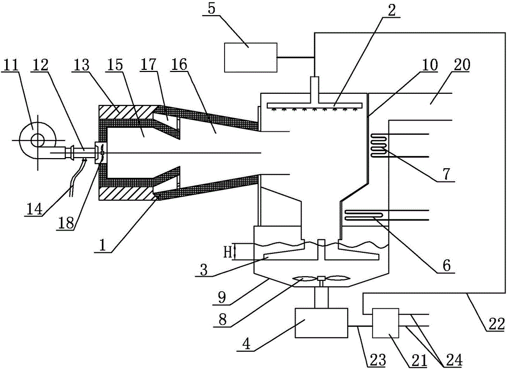
[0016] Specific implementation mode one: combine figure 1 Describe this embodiment, which includes a burner 1, a spray mechanism 2, a flue gas cooling pipe 3, a centrifugal slag remover 4, a flue gas condensation heat exchange coil 6, a heat pump heat exchange coil 7, and spoiler blades 8. The water tank 9, the spray tank body 10 and the flue 20, the spray tank body 10 and the centrifugal slag remover 4 are respectively arranged above and below the water tank 9, and the spray tank body 10 and the centrifugal slag remover 4 are all connected with each other. The water tank 9 is connected, the flue gas cooling pipe 3 is arranged in the water tank 9, and the flue gas cooling pipe 3 is installed at the lower end of the spray tank body 10, the spoiler blade 8 is arranged in the water tank 9, and the spoiler blade 8 is arranged in the centrifugal At the entrance of the slag remover 4, the flue 20 communicates with the water tank 9, the spray mechanism 2 is arranged on the top of the...

specific Embodiment approach 2

[0017] Specific implementation mode two: combination figure 1 This embodiment will be described. The secondary air blower 13 in this embodiment swirls the secondary air along the pre-combustion chamber 15 into the combustion chamber 16 . This design makes the secondary air be sent into the combustion chamber 16 after being preheated by the outer wall of the pre-combustion chamber 15, so as to increase the temperature of the secondary air. Other compositions and connections are the same as in the first embodiment.

specific Embodiment approach 3

[0018] Specific implementation mode three: combination figure 1 Describe this embodiment, in this embodiment, the shape of the flue gas heat dissipation pipe 3 is conical, the diameter of the upper end of the flue gas heat dissipation pipe 3 is smaller than the diameter of the lower end, and the lower end surface of the flue gas heat dissipation pipe 3 is provided with a plurality of small holes, each The diameter of each small hole is 20mm to ensure that the flow velocity of the flue gas exits the hole at 10m / s~15m / s. The flue gas cooling pipe 3 disperses the flue gas into small bubbles to directly contact with water for heat exchange. The small holes are used for water outlet, and the number of small holes can be arranged according to the unit capacity and operation needs. Other compositions and connections are the same as those in Embodiment 1 or Embodiment 2.


PUM


Abstract

The invention relates to a refrigerating and heating unit, and discloses a combustion unit allowing hot gas generated by pulverized coal combustion to be subjected heat exchange with water, in order to solve the problems that when the conventional refrigerating and heating unit operates, heat loss is high, components of smoke emissions are not environment-friendly, and heat exchange surfaces consume more materials. The combustion unit is characterized in that a spray tank body and a centrifugal deslagging machine are arranged above and below a water tank respectively, and communicate with the water tank; smoke radiating pipes are arranged in the water tank, and are mounted at the lower end of the spray tank body; flow disturbance vanes are arranged at an inlet of the centrifugal deslagging machine; a flue communicates with the water tank; a spray mechanism is arranged at the top of the spray tank body; a heat pump heat exchange coil and a smoke condensation heat exchange coil are arranged in the flue from the bottom up; a combustor is arranged on the side wall of the spray tank body; a secondary air inlet is formed between a combustion chamber and a precombustion chamber; a secondary air fan is arranged at the secondary air inlet; and outlets of the precombustion chamber and the combustion chamber are gradually-shrunk type outlets. The combustion unit is used in places where heat supply, cooling and domestic hot water are required.

Description

technical field [0001] The invention relates to a refrigerating and heating unit, in particular to a combustion unit in which pulverized coal is burned to generate hot gas and exchange water. Background technique [0002] The working principle of the existing refrigeration and heating units is: the heat source generated by the combustion of pulverized coal is directly sprayed into the boiler body, and then exchanged. This operation mode has the following problems: [0003] (1) Large combustion heat loss: The boiler burns natural gas or oil, and the heat exchange system requires boiler conduction. In a coal-fired boiler, there will be incomplete combustion of solids. Even if the fuel is completely burned, its slag and smoke exhaust will be inevitable. Takes away most of the heat. [0004] (2) The exhaust gas temperature is very high, reaching 160°C (the national standard is below 110°C), which does not save energy. [0005] (3) Smoke components: The pollutants in the pulver...

Claims


Application Information

Patent Timeline
Patent Type & Authority Applications(China)
IPC IPC(8): F24H7/02F24H8/00F24H9/18F23D1/02F23J15/04
CPCF23D1/02F23D2201/10F23J15/04F23J2215/20F23J2217/50F24H7/0283F24H8/00F24H9/1845Y02B30/00
Inventor 孙杰民郝星宇
Owner 孙紫怡
Why Eureka
Try Eureka